High-NA projection lens

A technology of projection objective lens and negative lens, which is applied in the field of projection optics, can solve problems such as material type limitations, and achieve the effects of simple and compact structure, reduced system length, and improved lithography resolution

Active Publication Date: 2014-06-25
INST OF OPTICS & ELECTRONICS - CHINESE ACAD OF SCI
View PDF4 Cites 2 Cited by
  • Summary
  • Abstract
  • Description
  • Claims
  • Application Information

AI Technical Summary

Problems solved by technology

Therefore, in order to meet higher resolution, it is necessary to shorten the wavelength of the light source and increase the numerical aperture of the projection optical system. The variety will be very limited

Method used


Image

  • High-NA projection lens

Examples


Embodiment Construction

[0030] In order to better illustrate the purpose and advantages of the present invention, the present invention will be further described below in conjunction with the accompanying drawings and specific embodiments.

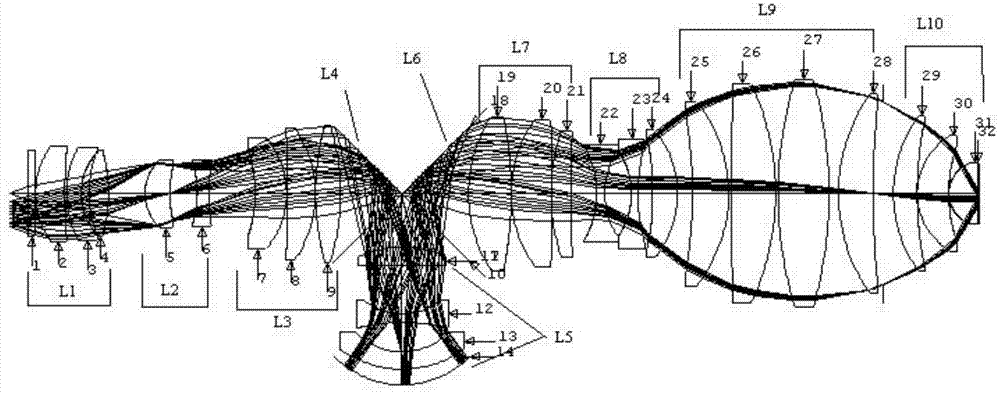
[0031] figure 1 It is a schematic diagram of the layout of the high NA projection objective lens of the present invention, 31 optical elements form the first unit L1, the second unit L2, the third unit L3, the fourth unit L4 and the fifth unit L5, the sixth unit L6, the seventh unit L7, An eighth unit L8, a ninth unit L9, and a tenth unit L10.

[0032] This high NA projection objective utilizes two flat mirrors to fold the optical system, effectively shortening the total system length. All the transmission mirrors in the present invention use fused silica material, and the refractive index of fused silica glass is 1.560491 at the central wavelength of 193 nm.

[0033] In order to meet the requirements of structural parameters and further improve the image quali...


PUM

PropertyMeasurementUnit
refractive indexaaaaaaaaaa

Abstract

The invention provides a high-NA projection lens used for enabling images of a mask surface to be formed in a silicon wafer surface. The high-NA projection lens is composed of a first unit, a second unit, a third unit, a fourth unit, a fifth unit, a sixth unit, a seventh unit, an eighth unit, a ninth unit and a tenth unit. The first unit L1, the second unit L2, the third unit L3, the fifth unit L5 and the eighth unit L8 have positive focal power. The seventh unit L7, the ninth unit L9 and the tenth unit L10 have negative focal power. The fourth unit L4 and the sixth unit L6 are plane mirrors, and the angle between each plane mirror and the horizontal plane is 45 degrees. By the high-NA projection lens, an object is formed to be an image where the object is shrunk by one fourth. The high-NA projection lens has the advantages of the high NA, high definition, compact structure, good imaging quality and the like.

Description

technical field [0001] The invention relates to an immersion type ultraviolet optical system used in a lithography process and a semiconductor element manufacturing device, belonging to the technical field of projection optics. Background technique [0002] Lithography is an integrated circuit manufacturing technology. It uses the principle of optical projection image to transfer the high-resolution graphics on the mask plate to the optical exposure process of the rubber-coated silicon wafer by means of exposure. Almost all integrated circuits Fabrication is done using optical projection lithography. Initially, semiconductor devices were manufactured using contact lithography technology in which masks were attached to silicon wafers. In 1957, contact lithography technology realized the manufacture of DRAM with a feature size of 20 microns. After that, the semiconductor industry introduced proximity lithography technology with a certain gap between the mask and the silicon ...

Claims


Application Information

Patent Timeline
Patent Type & Authority Applications(China)
IPC IPC(8): G02B13/18G02B13/14G02B13/00G02B17/08G03F7/20
Inventor 白瑜邢廷文吕保斌邓超朱红伟廖志远
Owner INST OF OPTICS & ELECTRONICS - CHINESE ACAD OF SCI
Why Eureka
Try Eureka