Immersed ultraviolet optical system

An optical system, immersion technology, applied in the field of projection optics, can solve problems such as material type restrictions, and achieve the effect of improving system resolution, improving imaging quality, and high telecentricity

Inactive Publication Date: 2015-02-18
INST OF OPTICS & ELECTRONICS - CHINESE ACAD OF SCI
View PDF5 Cites 0 Cited by
  • Summary
  • Abstract
  • Description
  • Claims
  • Application Information

AI Technical Summary

Problems solved by technology

Therefore, in order to meet higher resolution, it is necessary to shorten the wavelength of the light source and increase the numerical aperture of the projection optical system. The variety will be very limited

Method used


Image

  • Immersed ultraviolet optical system
  • Immersed ultraviolet optical system

Examples


Embodiment Construction

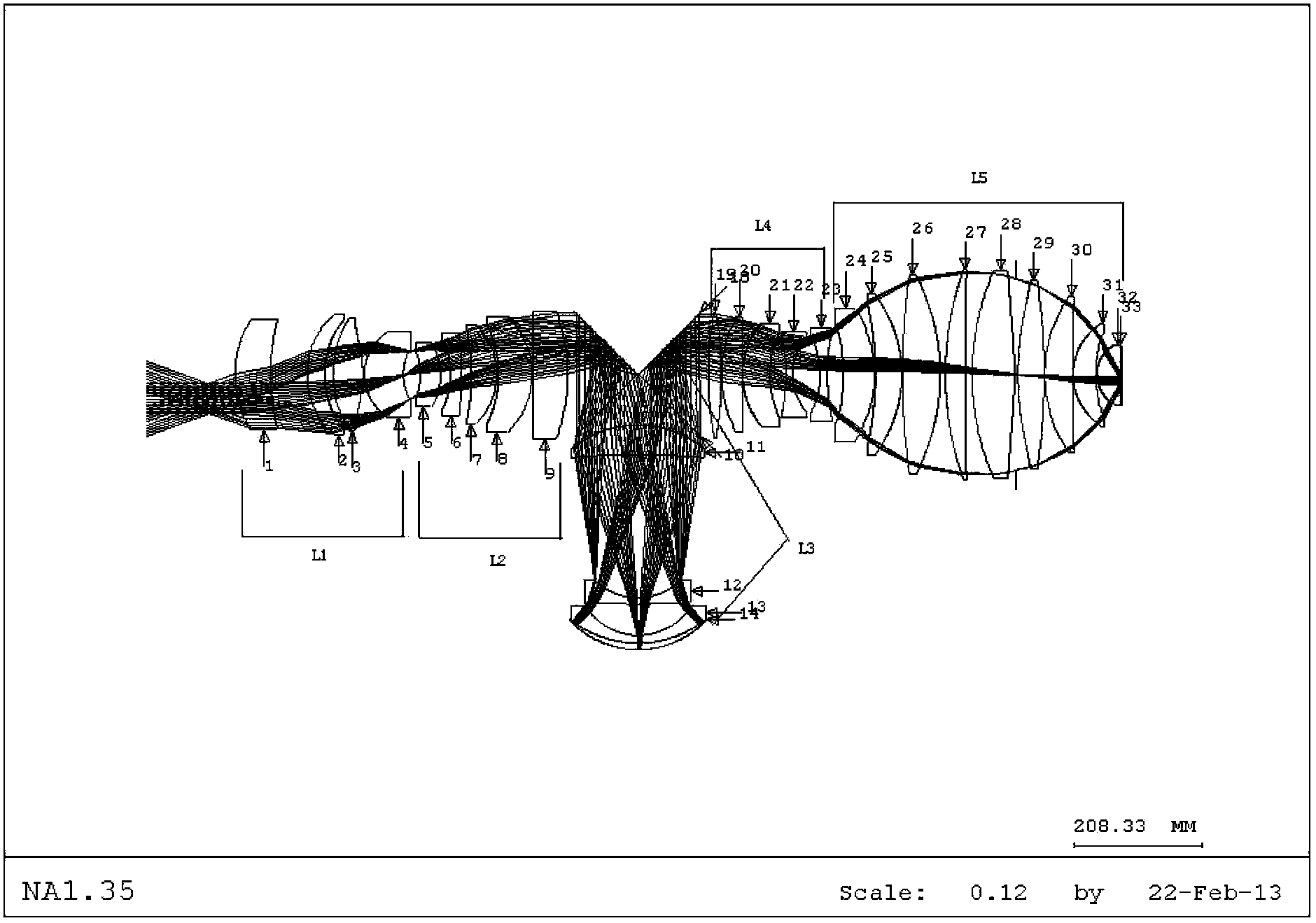
[0026] Such as figure 1 As shown, it is a schematic diagram of the layout of the immersion ultraviolet optical system of the present invention. 32 optical elements form the first unit L1, the second unit L2, the third unit L3, the fourth unit L4 and the fifth unit L5, which are arranged sequentially from the beam incident direction .

[0027] The first unit L1 is a unit group with positive refractive power, including a first positive lens 1 , a second positive lens 2 , a third positive lens 3 and a fourth positive lens 4 . The light is projected onto the first positive lens 1 and converged by the first positive lens 1 , then converged by the second positive lens 2 and then reaches the third positive lens 3 , and is incident on the fourth positive lens 4 after being converged by the first negative lens 3 .

[0028] The second unit L2 is a unit group with positive refractive power, including a fifth positive lens 5 , a first negative lens 6 , a sixth positive lens 7 , a seventh...


PUM

PropertyMeasurementUnit
refractive indexaaaaaaaaaa

Abstract

The invention provides an immersed ultraviolet optical system, which is used for forming an image of an object plane into an image plane. The immersed ultraviolet optical system comprises a first unit, a second unit, a third unit, a fourth unit and a fifth unit in the direction of an optical axis of the system. The first unit group L1 with positive refractive power, the second unit group L2 with positive refractive power, the third unit group L3 with positive refractive power, the fourth unit group L4 with negative refractive power and the fifth unit group L5 with negative refractive power are orderly arranged in the incidence direction of light beams. The immersed ultraviolet optical system provided by the invention can compensate aberration better, improve imaging quality, promote system resolution and improve photoetching efficiency.

Description

technical field [0001] The invention relates to an immersion type ultraviolet optical system used in a lithography process and a semiconductor element manufacturing device, belonging to the technical field of projection optics. Background technique [0002] Lithography is an integrated circuit manufacturing technology. It uses the principle of optical projection image to transfer the high-resolution graphics on the mask plate to the optical exposure process of the rubber-coated silicon wafer by means of exposure. Almost all integrated circuits Fabrication is done using optical projection lithography. Initially, semiconductor devices were manufactured using contact lithography technology in which masks were attached to silicon wafers. In 1957, contact lithography technology realized the manufacture of DRAM (Dynamic Random Access Memory) with a Feature Size of 20 microns. After that, the semiconductor industry introduced proximity lithography technology with a certain gap be...

Claims


Application Information

Patent Timeline
Patent Type & Authority Patents(China)
IPC IPC(8): G03F7/20G02B13/00G02B13/18G02B13/22G02B1/00
Inventor 白瑜邢廷文朱红伟吕保斌邓超廖志远冉英华
Owner INST OF OPTICS & ELECTRONICS - CHINESE ACAD OF SCI
Why Eureka
Try Eureka