Projection optical system

A projection optical system and the same technology, applied in the field of high-resolution projection optical systems, can solve the problems of low resolution of projection optical systems, reduce the difficulty of processing and assembly, and high detection accuracy, so as to improve the quality of objective lenses, reduce the difficulty of assembly, and The effect of precision and simplification of manufacturing process

Inactive Publication Date: 2012-07-11
INST OF OPTICS & ELECTRONICS - CHINESE ACAD OF SCI
View PDF4 Cites 10 Cited by
  • Summary
  • Abstract
  • Description
  • Claims
  • Application Information

AI Technical Summary

Problems solved by technology

[0008] In order to solve the problems of low resolution of the existing projection optical system, high processing cost, high detection accuracy, and difficult assembly and adjustment, the present invention proposes a deep ultraviolet projection optical system, which has a compact structure and a large viewing angle. Field and imaging quality are excellent, all lenses are spherical mirrors, which reduces the difficulty of processing and assembly

Method used


Image

  • Projection optical system
  • Projection optical system
  • Projection optical system

Examples


Embodiment Construction

[0027] In order to better illustrate the purpose and advantages of the present invention, the present invention will be further described below with reference to the accompanying drawings and specific embodiments.

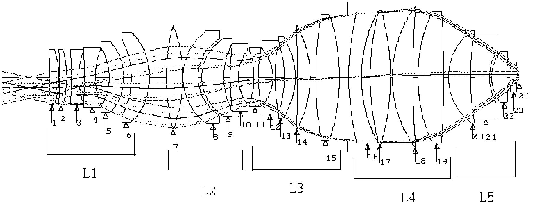
[0028] figure 1 It is a schematic diagram of the layout of the global projection objective lens of the present invention. 23 global lenses form a first lens unit L1, a second lens unit L2, a third lens unit L3, a fourth lens unit L4 and a fifth lens unit L5, which are sequentially incident from the light beam. Orientation settings.

[0029] The first lens unit L1 is a lens group with negative refractive power, including a first positive lens 1, a second positive lens 2, a first negative lens 3, a second negative lens 4, a first meniscus lens 5 and a second meniscus Lens 6. The light is projected to the first positive lens 1 and then converged by the first positive lens 1, then converged by the second positive lens 2 and then reaches the first negative lens 3, div...


PUM

PropertyMeasurementUnit
refractive indexaaaaaaaaaa

Abstract

The invention discloses a projection optical system which is used for imaging images in an object plane into an image plane. The projection optical system sequentially comprises a first lens unit (L1), a second lens unit (L2), a third lens unit (L3), a fourth lens unit (L4) and a fifth lens unit (L5) which are arranged in the direction of the optical axis of the system; the lens units are positioned in the same optical axis; the first lens unit (L1) has negative refractive power; the second lens unit (L2) has positive refractive power; the third lens unit (L3) has negative refractive power; the fourth lens unit (L4) has positive refractive power; the fifth lens unit (L5) has positive refractive power; and all lenses adopt spherical surfaces. The projection optical system can better compensate aberration, improve the imaging quality, enhance the system resolution and improve the photolithography efficiency.

Description

technical field [0001] The invention relates to a deep-ultraviolet global projection optical system used in a lithography process and a semiconductor element manufacturing device, and belongs to the technical field of high-resolution projection optical systems. Background technique [0002] Lithography is an integrated circuit manufacturing technology. It uses the principle of optical projection imaging to transfer the high-resolution graphics on the mask plate to the glue-coated silicon wafer by exposure. Almost all integrated circuits are manufactured using optical technology. Projection Lithography. Initially, semiconductor devices were fabricated using contact lithography techniques in which masks were attached to silicon wafers. In 1957, contact lithography realized the manufacture of dynamic random access memory (DRAM, Dynamic Random Access Memory) with a feature size of 20 microns. After that, the semiconductor industry introduced proximity lithography with a certai...

Claims


Application Information

Patent Timeline
Patent Type & Authority Applications(China)
IPC IPC(8): G02B13/14G02B13/22G02B3/00G02B7/02G02B27/18G03F7/20
Inventor 白瑜邢廷文吕保斌范真节邓超张海波
Owner INST OF OPTICS & ELECTRONICS - CHINESE ACAD OF SCI
Why Eureka
Try Eureka