Amplification display device and amplification display system
A display device and display system technology, applied in optical components, optics, instruments, etc., can solve the problems of complex technology, high cost, and difficulty in commercialization, and achieve the effects of easy productization, low cost, and simple manufacturing process
- Summary
- Abstract
- Description
- Claims
- Application Information
AI Technical Summary
Problems solved by technology
Method used
Image

Examples
Embodiment 1
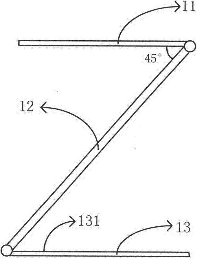
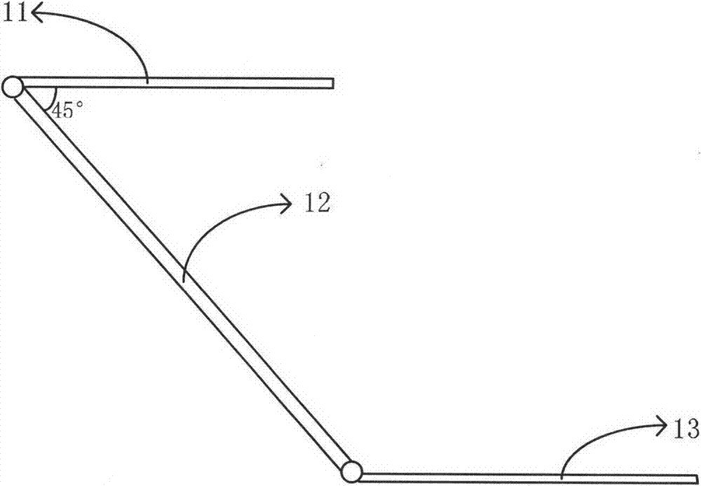
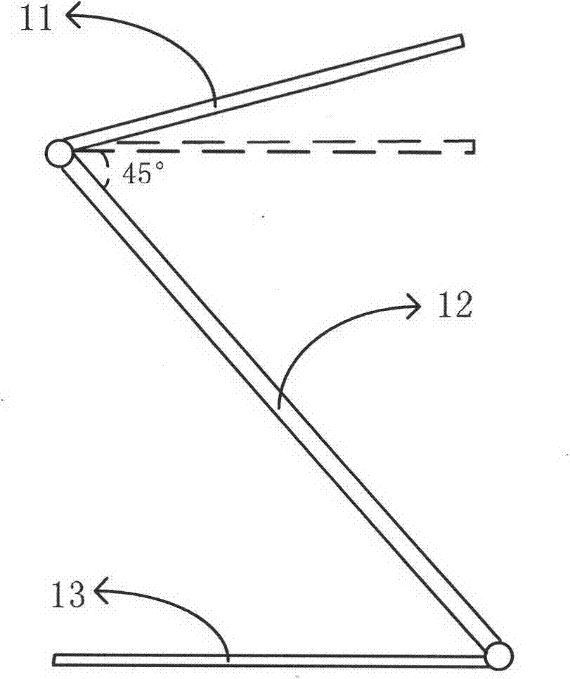
[0041] The present invention provides an amplified display device, such as figure 1 As shown, it includes: an upper support body 11 , a lower support body 13 and a transflective device 12 connected between the upper support body 11 and the lower support body 13 . Wherein, the upper supporting body 11 is used for placing electronic display devices. The specific structure of the upper support body 11 can be designed according to the structure of the electronic display device, and any structure capable of placing the electronic display device on the upper support body 11 is acceptable, and its specific structure is not limited here. For example, the electronic display device may be a device with 2D or 3D display function, such as a mobile phone, a tablet computer, a notebook computer, and a game console. The corresponding upper support body 11 can be a bracket that matches the shape and size of the mobile phone and other equipment placed on it.
[0042]The transflective device...
Embodiment 2
[0050] An amplified display device, such as Figure 5 As shown, it includes a first accommodating structure 11 , a second accommodating structure 13 , a first connection structure (not shown in the figure), an active connection structure and a transflective device 12 . The first accommodating structure 11 is used for accommodating an electronic display device. The first accommodating structure 11 includes a connecting end 21a and a free end 21b opposite to the connecting end 21a. The transflective device 12 includes a first end 51 and a free end 21b opposite to the end. The second end 52, and the transflective device 12 also includes a first surface 53 and a second surface 54 opposite to the first surface, the first surface 53 faces the first accommodating structure 11, and the second surface 54 faces In the second housing structure 13, the first end 51 of the transflective device 12 is connected to the connecting end 21a of the first housing structure 11 through the first con...
Embodiment 3
[0060] An amplified display device, such as Figure 6As shown, the difference from Embodiment 1 and Embodiment 2 is that the electronic display device can display naked-eye stereoscopic images. The augmented display device further includes a first image processing unit 20 configured to mirror the image displayed by the electronic display device along the horizontal central axis. Specifically, assuming that the number of pixels in the horizontal direction of each image on the display screen of the electronic display device is W, then the pixel value of any pixel point A (Xa, Ya) in each image is compared with the pixel point B (W- The pixel values of Xa, Ya) are swapped. From Figure 6 It can be seen from the optical path diagram in that, due to the imaging effect of the transmissive mirror 105, the positions of the image points E and F without the transmissive reflective mirror 105 and the positions of the image points E' and F' after the transmissive reflective mirror are...
PUM
 Abstract
Description
Claims
Application Information
 - R&D
- Intellectual Property
- Life Sciences
- Materials
- Tech Scout
- Unparalleled Data Quality
- Higher Quality Content
- 60% Fewer Hallucinations
Browse by: Latest US Patents, China's latest patents, Technical Efficacy Thesaurus, Application Domain, Technology Topic, Popular Technical Reports.
© 2025 PatSnap. All rights reserved.Legal|Privacy policy|Modern Slavery Act Transparency Statement|Sitemap|About US| Contact US: help@patsnap.com