
Switch device and method for measuring transmission delay through FPGA

A measurement method and transmission delay technology, applied in transmission systems, digital transmission systems, data exchange networks, etc., can solve problems such as inability to judge the synchronization of sampling data, and achieve the effect of saving construction costs and reducing the number of optical ports

Inactive Publication Date: 2014-06-25
BEIJING SIFANG JIBAO AUTOMATION
View PDF5 Cites 32 Cited by
  • Summary
  • Abstract
  • Description
  • Claims
  • Application Information

AI Technical Summary

Problems solved by technology

[0004] In the networking mode, the transmission of the SV sampling data message depends on the switch, and the transmission delay of the message in the switch is uncertain, so the relay protection device can only realize protection based on the CNT absolute time stamp in the SV message Function, because the CNT absolute time scale comes from the clock system in the substation, so when the external clock is abnormal, the relay protection device across the interval cannot judge whether the sampling data is synchronized, and can only block the protection function

Method used


Image

  • Switch device and method for measuring transmission delay through FPGA
  • Switch device and method for measuring transmission delay through FPGA
  • Switch device and method for measuring transmission delay through FPGA

Examples


Embodiment Construction

[0035] The present invention will be further described below in conjunction with the accompanying drawings.

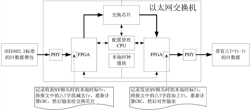
[0036] This application discloses a switch device that uses programmable logic array FPGA to realize measurable transmission delay, as shown in the attached figure 2 shown.

[0037] The switch device includes an Ethernet switching chip, an input programmable logic array FPGA, an output programmable logic array FPGA, an input Ethernet PHY chip, an output Ethernet PHY chip, a configuration management CPU and a local clock module.

[0038] The function of the Ethernet PHY chip at the input end and the output end is to realize the physical layer interface of the switch device, and to complete the encoding and decoding conversion of the FPGA data stream and the Ethernet data frame on the external Ethernet.

[0039] The input FPGA automatically screens out the input SV message, can accurately measure the local time stamp Tr at the input time of the SV message, and adds Tr ...


PUM


Abstract

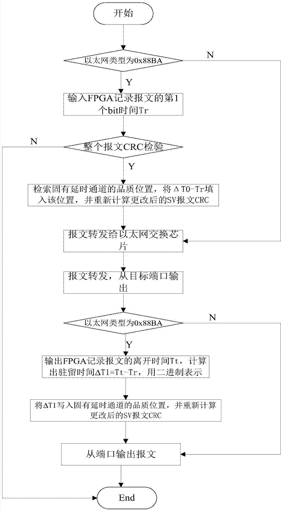
The invention provides a switch device and method for measuring transmission delay through an FPGA. The switch device is characterized in that as for an SV sample data raw package meeting the IEEE802.3 standard, the FPGA inside a switch records the moment Tr when the first bit of a message enters a port of the switch and the moment Tt when the first bit of the message is transmitted out from the port of the switch, the timestamp accuracy is in the nanosecond grade, the FPGA calculates the residence time deltaT of the message in the switch according to the formula deltaT=Tt-Tr, and the residence time deltaT is written into a designated position in the SV message. According to the switch device and method, the problem that timing of a relay protection device in an intelligent substation in the networking mode must depend on an external clock is solved, the fundamental principle that SV sample data are synchronized by a use device is reflected, and the theory is equivalent to that of the mode that the SV sample data are directly transmitted without the switch.

Description

technical field [0001] The invention belongs to the technical field of process layer digitization of intelligent substations, in particular to the scenario where SV sampling data is transmitted through a switch based on a publish / subscribe mechanism. Background technique [0002] SV (sample value) is the abbreviation of the digitized sampling data transmitted by the process layer of the smart substation in the smart grid. [0003] At present, the relay protection of smart substations adopts the networking mode to transmit SV sampling data packets. The obstacle is that the relay protection across intervals must rely on external clocks to ensure the synchronization of sampling data. , the cross-interval relay protection will quit running. [0004] In the networking mode, the transmission of the SV sampling data message depends on the switch, and the transmission delay of the message in the switch is uncertain, so the relay protection device can only realize protection based o...

Claims


Application Information

Patent Timeline
Patent Type & Authority Applications(China)
IPC IPC(8): H04L12/26H04L12/931
Inventor 袁海涛徐刚胡炯侯志光肖正强徐万方
Owner BEIJING SIFANG JIBAO AUTOMATION
Learn More