
Device and method used for controlling jitter buffer

A technology of jitter buffer and controller, applied in the direction of output power conversion device, current collector, access restriction, etc., can solve problems such as multi-delay

Inactive Publication Date: 2014-06-25
DOLBY LAB LICENSING CORP
View PDF1 Cites 14 Cited by
  • Summary
  • Abstract
  • Description
  • Claims
  • Application Information

AI Technical Summary

Problems solved by technology

Obviously, it can introduce too much latency if large latency fluctuations need to be accommodated

Method used


Image

  • Device and method used for controlling jitter buffer
  • Device and method used for controlling jitter buffer
  • Device and method used for controlling jitter buffer

Examples


no. 8 approach

[0150] According to an eighth embodiment of the present application, the method may further include: estimating the long-term length of each frame ( Figure 15 in operation 1512 or operation 1514). Since the long-term length is calculated based on the delay jitter value of the past frame, the reception of the new frame ( Figure 15 operation 1502) to trigger the computation or update of the long-term length.

[0151] As a variant, in order to avoid the bad quality of the previous speech segment from increasing the long-term length (and thus increasing the jitter buffer instantaneous length) too much, at the beginning of a new speech segment ("YES" in operation 1504) Provides an opportunity to trim jitter buffers that are too long. That is, when the long-term length at the end of the last speech segment is greater than the predetermined threshold Th1 ("Yes" in operation 1508), the long-term length may be reset to an initial value and the historical delay jitter value may be cle...


PUM


Abstract

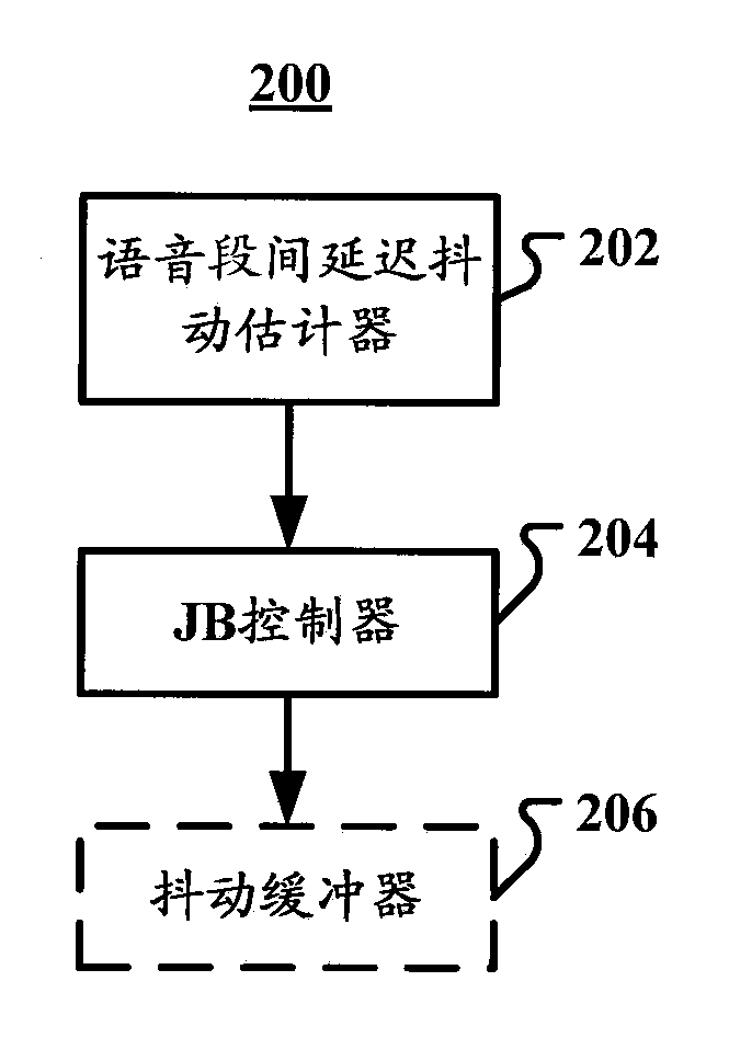
Described are a device and method used for controlling a jitter buffer. In one execution mode, the device used for controlling the jitter buffer includes an inter-voice-segment delay jitter estimator which is used for estimating an offset value of a delay of a first frame in a current voice segment relative to a delay of a last anchor frame in a prior voice segment; and a jitter butter controller which is used for adjusting the length of the jitter buffer on the basis of a long-term length of each frame of the jitter buffer and the offset value.

Description

technical field [0001] The present application relates generally to audio signal processing. More specifically, embodiments of the present application relate to an apparatus and method for controlling a jitter buffer. Background technique [0002] Due to highly non-uniform network conditions, voice transmission over packet networks suffers from fluctuations in latency, commonly referred to as jitter. In IP-based networks, fixed delays can be attributed to algorithmic, processing, and propagation delays due to material and distance, whereas variable delays are due to fluctuations in IP network information traffic, different transmission paths on the Internet, etc. caused by. VoIP (Voice over Internet Protocol) receivers often rely on "jitter buffers" to combat the negative effects of jitter. Here, packet (packet) delay fluctuation or jitter is defined as the time difference between the actual arrival time of a packet and a reference clock at normal packet rates. By introd...

Claims


Application Information

Patent Timeline
IPC IPC(8): H04L12/885H04L49/9023H04L47/2416H04L47/56
CPCH04L65/80H04L47/2416H04L47/283B60L53/14B60L55/00B60L2210/30B60L2210/40H02M1/007H02M1/14H02M1/42H02M7/4807H02M7/79Y02E60/00Y02T10/70Y02T10/7072Y02T10/72Y02T90/14Y04S10/126H04L47/56B60L1/00H02M5/458H04L1/205H04L43/087H04W16/18H04W24/02H04W28/02H04W48/18H04W72/04H04W72/12Y02B70/10
Inventor 孙学京双志伟
Owner DOLBY LAB LICENSING CORP
Learn More