Oil-water separator for heat treatment production line

An oil-water separator and production line technology, applied in liquid separation, separation methods, chemical instruments and methods, etc., can solve problems such as affecting the appearance of workpieces, oil splashing, loss of function, etc., achieving a high degree of automation, a wide range of uses, and simple operation. Effect

Inactive Publication Date: 2014-07-02
HEPHAES HEAT TREATMENT SYST JIANGSU
View PDF4 Cites 5 Cited by
  • Summary
  • Abstract
  • Description
  • Claims
  • Application Information

AI Technical Summary

Problems solved by technology

Due to the limited oil absorption efficiency of the oil absorption plate, the oil-water separation effect is not good, and the oil absorption plate will reach saturation after working for a long time, and it will lose its function if it is not cleaned in time
This kind of oil-water separator has a large volume and low oil-water separation efficiency. It needs to be cleaned frequently, and the separated water contains a certain amount of oil.
When using water containing oil to clean the workpiece, the cleaning will not be clean, and the next tempering process will produce a lot of oily smoke, which will not only affect the appearance of the workpiece, but also pollute the tempering furnace and affect the quality of tempering
When using the separated oil for secondary use, if the oil contains too much water, it will affect the heat treatment effect, causing soft spots, quenching cracks or deformation of the parts, or oil splashing, resulting in safety accidents

Method used


Image

  • Oil-water separator for heat treatment production line
  • Oil-water separator for heat treatment production line
  • Oil-water separator for heat treatment production line

Examples


Embodiment 1)

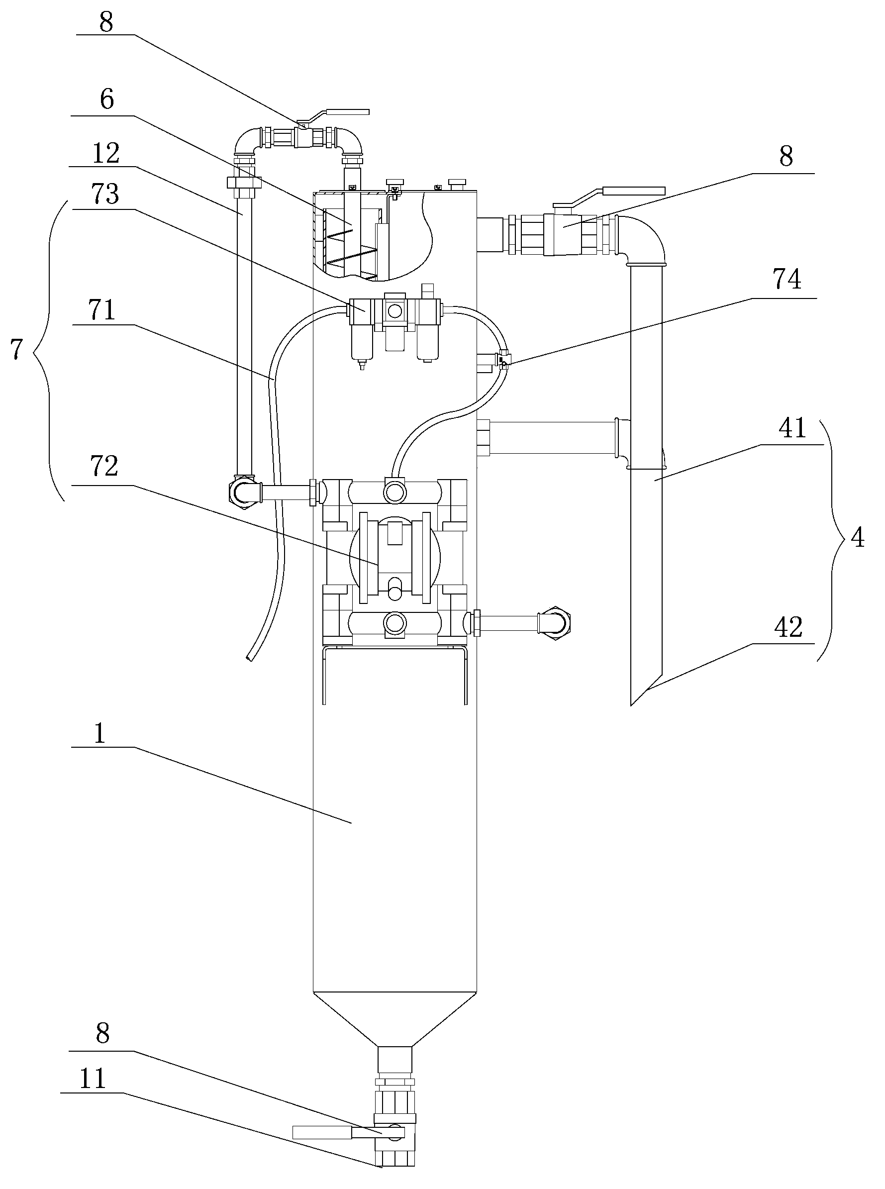
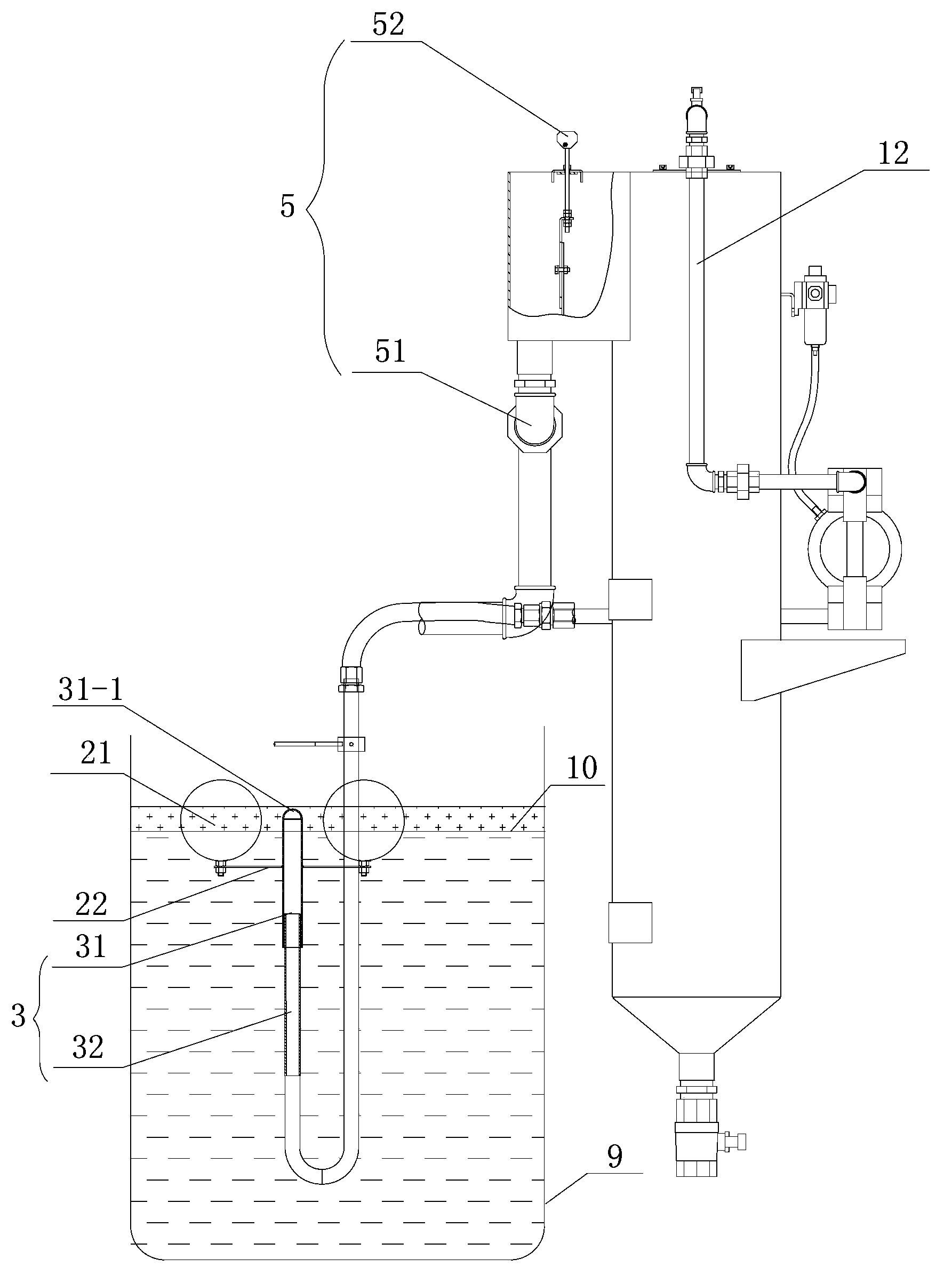
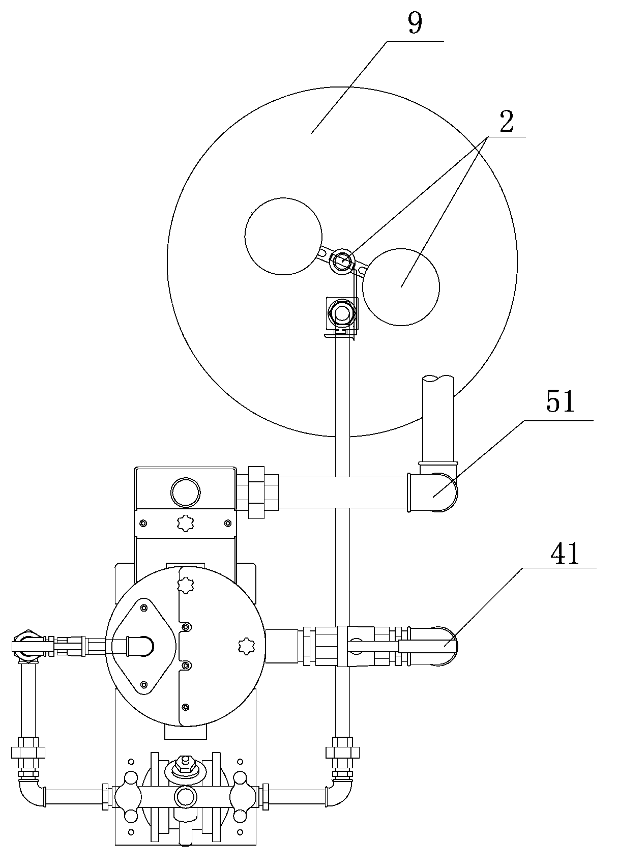
[0024] See Figure 1 to Figure 3 , the present invention has a vertically arranged cylindrical barrel 1 and an oil absorbing device 3 connected to the barrel 1 through a pipeline. The oil absorbing device 3 is located in the oil-water tank 9 next to the barrel 1. Position tracking device 2; also includes oil discharge device 4 and drainage device 5, oil discharge device 4 and drainage device 5 are connected to cylinder 1 through pipes; Oil suction starting device 7 is arranged. The lower part of the cylinder body 1 is frustum-shaped, and the lower end of the cylinder body 1 is provided with a sewage outlet 11, which is used to discharge the remaining solid dirt after oil-water separation. A stainless steel ball valve 8 is provided between the sewage outlet 11 and the cylinder body 1, which can facilitate the control of sewage discharge.

[0025] The oil suction device 3 comprises an oil suction sleeve 31 and an oil suction pipe 32 with an oil suction port 31-1 on the upper e...


PUM


Abstract

The invention relates to oil-water separation equipment, in particular to an oil-water separator for a heat treatment production line. The oil-water separator comprises a barrel body arranged vertically and an oil suction device connected with the barrel body by a pipeline, as well as an oil discharge device and a water draining device, wherein the oil suction device is positioned in an oil-water tank nearby the barrel body, and a floating ball type liquid level tracking device is also arranged at the tail end of the oil suction device; the oil discharge device and the water draining device are connected with the barrel body by a pipeline; a helical fin-shaped damping pipe is arranged in the barrel body, and an oil suction starting device is arranged outside the barrel body. The floating ball type liquid level tracking device is additionally arranged, an oil suction sleeve and an oil suction pipe are in sliding connection, the oil suction sleeve can move up and down along with a floating ball to precisely and automatically track the oil-water interface and ensure that the level height of an oil-water inlet is consistent to the oil-water interface; a substance entering the pipeline is oil essentially and only contains little water; secondary separation can be carried out in the barrel body and thorough oil-water separation effect is achieved.

Description

technical field [0001] The invention relates to an oil-water separation device, in particular to an oil-water separator for a heat treatment production line. Background technique [0002] Quenching is a heat treatment process in which the metal is heated to a certain temperature above the critical temperature, held for a certain period of time to make it austenitized in whole or in part, and then rapidly cooled to below Ms at a cooling rate greater than the critical cooling rate for martensitic transformation. Cooling requires a certain cooling medium, commonly used mineral oil, water or oil-water mixture. After the metal workpiece is quenched with oil or oil-water mixture, the surface needs to be cleaned before the next step, and the surface of the metal workpiece also needs to be cleaned before heat treatment. At first, it was cleaned manually, and later a washing machine was invented, which can be cleaned automatically by a washing machine. The oil stain on the surface ...

Claims


Application Information

Patent Timeline
Patent Type & Authority Applications(China)
IPC IPC(8): B01D17/032
Inventor 杨爱斌李哨国华公平
Owner HEPHAES HEAT TREATMENT SYST JIANGSU
Why Eureka
Try Eureka