Printing head and three-dimensional printing machine

A technology of 3D printers and print heads, which is applied in the direction of processing and manufacturing, coating devices, manufacturing tools, etc., can solve the problems of reducing printing quality, achieve the effects of improving printing quality, meeting high-speed printing requirements, and reducing vibration

Active Publication Date: 2014-07-02
PRINT RITE UNICORN IMAGE PROD CO LTD
View PDF9 Cites 17 Cited by
  • Summary
  • Abstract
  • Description
  • Claims
  • Application Information

AI Technical Summary

Problems solved by technology

In order to achieve multi-color printing, not only the quality of the print head is increased, but also the vibration source that causes the v

Method used


Image

  • Printing head and three-dimensional printing machine
  • Printing head and three-dimensional printing machine
  • Printing head and three-dimensional printing machine

Examples


no. 1 example

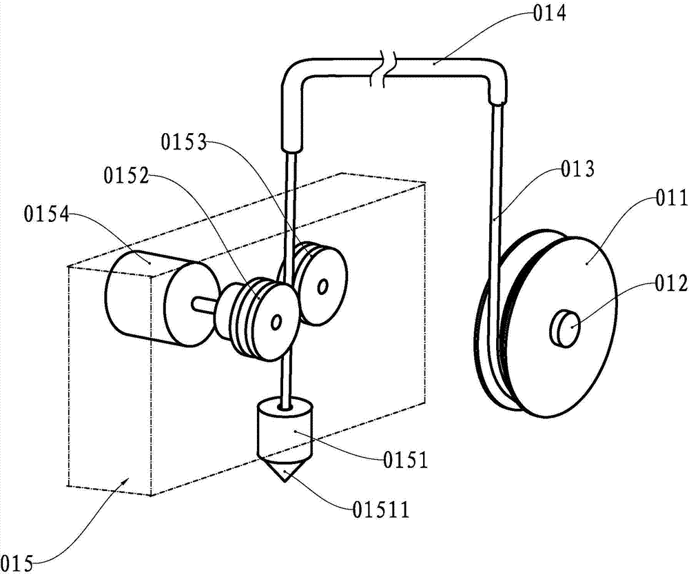
[0029] see Figure 4, The print head is composed of a printing nozzle 1, a hose 2, a heater 3, a feeding device 4, a cooling device 5 and a feeding pressure device 6. The outlet of the heater 3 communicates with the inlet of the printing nozzle 1 through the hose 2, which is a high-temperature-resistant lightweight hose, and is used to heat the molten material in the heating and melting chamber 31 of the heater 3 to a molten state. The molding material is introduced into the printing nozzle 1; the feeding device 4 has a pair of feeding rollers located near the feeding port of the heater 3, and is used to feed the fine material on the filament box of the 3D printer under the control of the 3D printer controller. The wire is sent into the heating and melting chamber 31 at a certain rate; the cooling device 5 has a fan 51, and the airflow generated by the rotation of the fan 51 is used to regulate the temperature of the heater 3 and the connection between the heater 3 and the fee...

no. 2 example

[0031] As an explanation of the second embodiment of the print head of the present invention, only the differences from the above first embodiment of the print head will be described below.

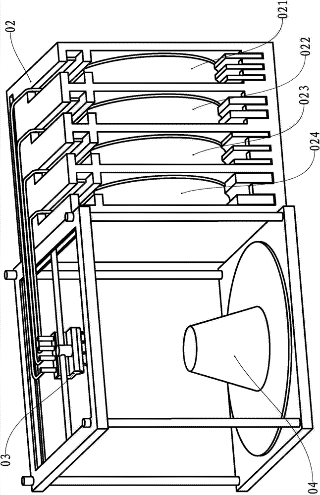
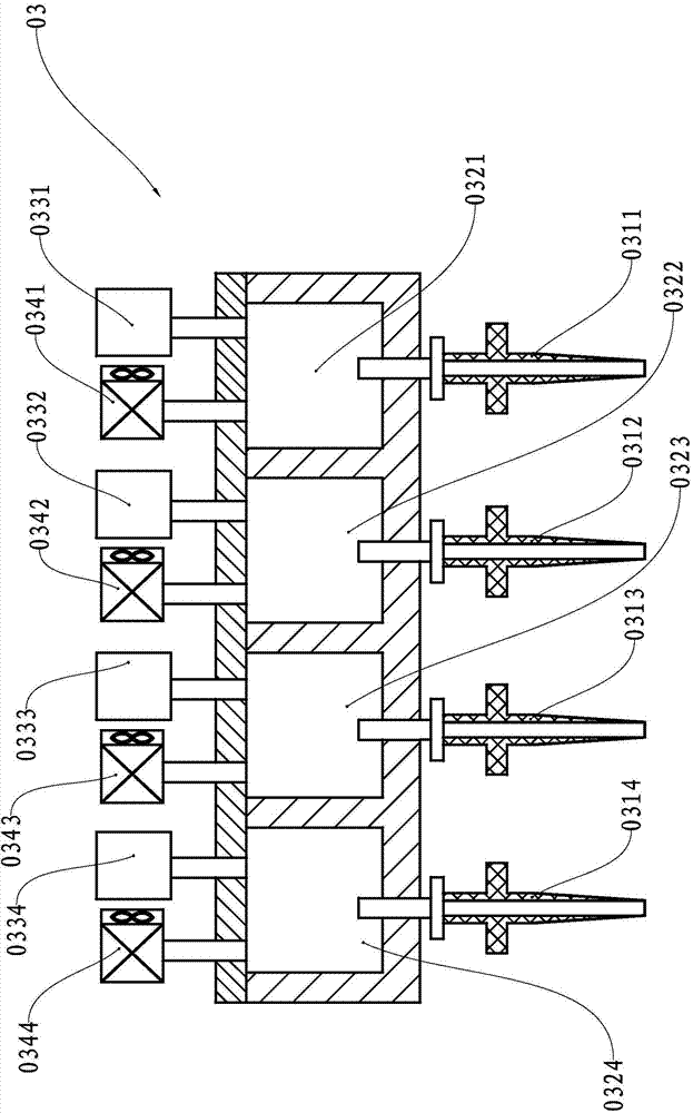
[0032] see Figure 5 and Image 6 , the number of printing nozzles, hoses, heating and melting chambers of heaters, feeding devices, cooling devices and feeding pressure devices of the printing head in this example are four, which are respectively printing nozzles 211, 212, 213 and 214, soft Tubes 221, 222, 223 and 224, heating and melting chambers 231, 232, 233 and 234 of heaters, feeding devices 241, 242, 243 and 244, cooling devices 251, 252, 253 and 254, and feed pressure devices 261 . The form connects the print nozzle and the heater.

no. 3 example

[0034] As a description of the third embodiment of the present invention, only the differences from the first embodiment of the above-mentioned print head will be described below. The print head of this example is also provided with a negative pressure device for providing a heating and melting chamber for the heater. Negative pressure, after the target molding is printed, the molding material in the printing nozzle and hose is sucked back into the heating and melting chamber, which effectively prevents the residual molding material from condensing in the hose and printing nozzle, hindering subsequent printing.


PUM


Abstract

The invention relates to a printing head for melting a sedimentation-type rapid molding device. The printing head comprises a printing nozzle, a heater and a feeding device, wherein a discharge hole of the feeding device is communicated with a feed hole of the heater; the printing nozzle is mounted on a printing vehicle of a three-dimensional printing machine; the heater is mounted on a stander of the three-dimensional printing machine; the discharge hole of the heater is communicated with the feed hole of the printing nozzle through a hose, so that molding materials in a molten state in a heating melting chamber of the heater are conveyed into the printing nozzle through the high-temperature-resistant hose; a feeding pressure device is used for supplying feeding pressure to the heating melting chamber of the heater. By adopting the printing head, vibration of the printing nozzle of the printing head during printing is reduced and the quality of the printer is improved. Besides, the invention also provides the three-dimensional printing machine comprising the printing head.

Description

technical field [0001] The invention relates to a component of a rapid prototyping device and a rapid prototyping device comprising the component, in particular to a print head for a fused deposition type rapid prototyping device and a three-dimensional printer comprising the print head. Background technique [0002] A three-dimensional printer is a device based on a digital model that uses materials such as powdered metal or plastic to construct three-dimensional objects by layer-by-layer printing. One of the three-dimensional printers is to supply molding materials to the printing head in the form of filaments. The molding materials are heated to a molten state by means of electric heating in the printing head. The moving path prints out the 3D object layer by layer. [0003] The background technology of the patent document whose notification number is CN1216726C describes a kind of three-dimensional printer that supplies molding materials to the printing head in the form...

Claims


Application Information

Patent Timeline
IPC IPC(8): B29C67/00
CPCB33Y30/00B29C64/209B29C64/118B29C64/106
Inventor 何永刚
Owner PRINT RITE UNICORN IMAGE PROD CO LTD
Why Eureka
Try Eureka