Freeze dryer

A freeze-drying machine and freeze-drying technology, which is applied in the field of freeze-drying machines, can solve the problems of inconvenient assembly and transportation, difficult manufacturing and assembly, and large space occupation, and achieve the effects of avoiding pollution risks, saving manufacturing materials, and occupying a small space

Active Publication Date: 2014-07-02
TRUKING TECH LTD
View PDF7 Cites 4 Cited by
  • Summary
  • Abstract
  • Description
  • Claims
  • Application Information

AI Technical Summary

Problems solved by technology

This kind of freeze dryer has the following disadvantages: 1. The freeze-drying box and the cold trap are connected through a connecting pipe, and the connecting pipe needs to open a large hole on the freeze-drying box and the cold trap, and install it with a large flange. The valve leads to complex structure, high cost, and difficult manufacturing and assembly. The driving cylinder of the on-off valve will also cause pollution to the product; 2. The freeze-drying box and the cold trap are two independent containers arranged horizontally side by side, and the manufacturing cost is high. , Take up a lot of space, and it is inconvenient to assemble and transport

Method used


Image

  • Freeze dryer
  • Freeze dryer
  • Freeze dryer

Examples


Embodiment 1

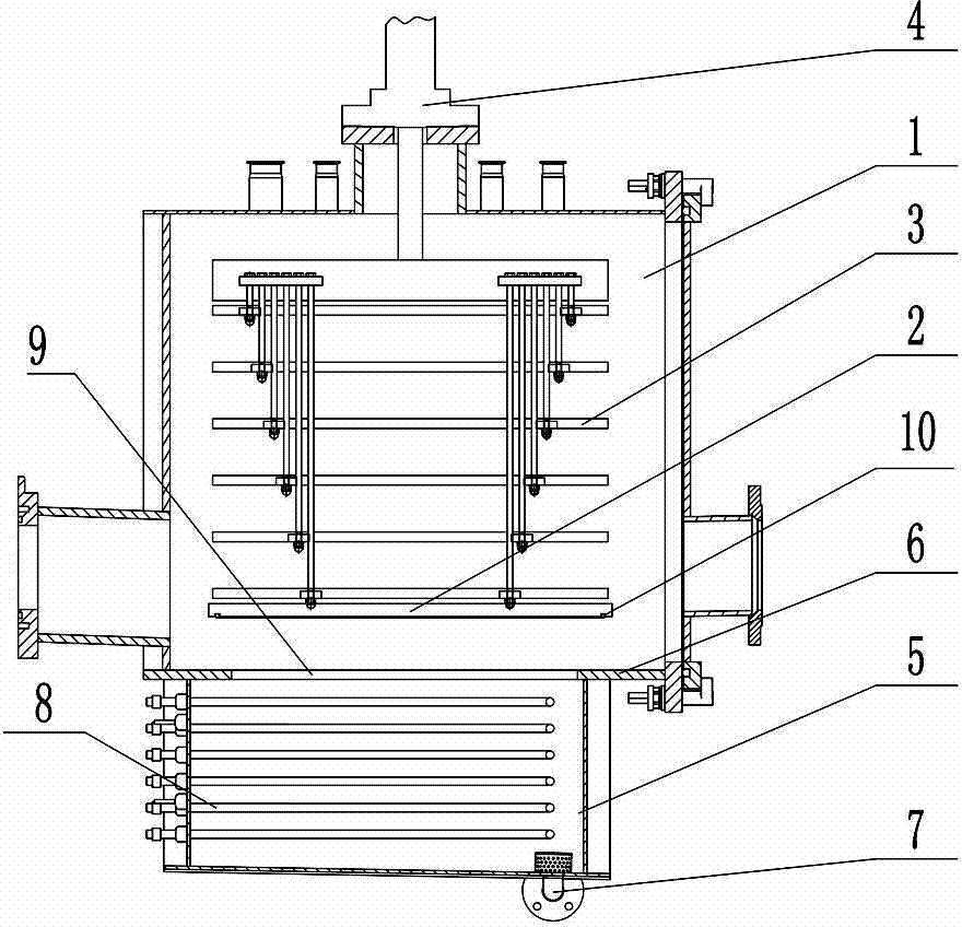
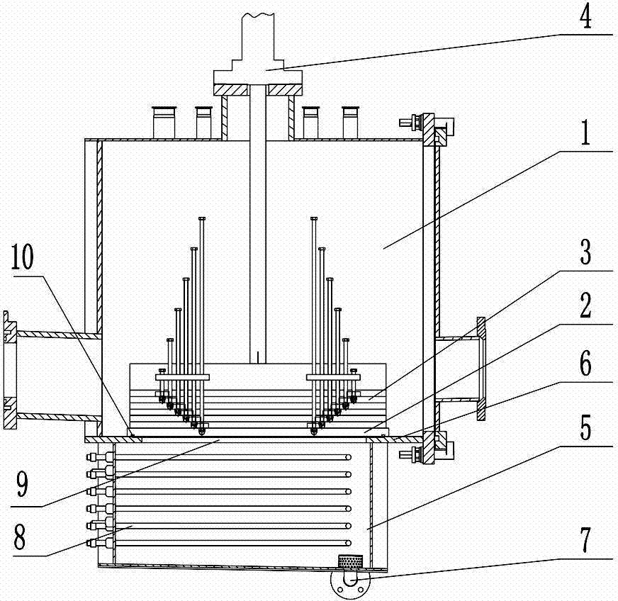
[0028] Such as figure 1 As shown, the lyophilizer of the present invention includes a freeze-drying chamber 1 and a cold trap chamber 5, and a coil 8 for refrigeration is provided in the cold-trap chamber 5; Above the multiple freeze-dried slabs 3, the top of the freeze-dried chamber 1 is provided with a lifting drive 4 for driving the support plate 2 and the freeze-dried slabs 3 up and down. The lifting drive 4 in this embodiment is an oil cylinder. During work, after the bottle body in a half-stoppered state completes freeze-drying on the freeze-drying plate layer 3, the support plate 2 and each freeze-drying plate layer 3 will move down under the drive of the lifting drive member 4, so that each freeze-drying plate layer The layers 3 are close to each other for plugging, and the rubber stopper on the bottle body is completely pressed into the bottle mouth; the support plate 2 is lowered to the bottom of the freeze-drying chamber 1 to support the freeze-dried plate layer 3 ....

Embodiment 2

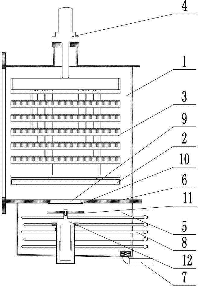
[0034] Such as image 3 and Figure 4 As shown, the present embodiment is basically the same as Embodiment 1, the only difference being that the sealing member in this embodiment is a sealing plate 11 located in the cold trap cavity 5, and the bottom of the cold trap cavity 5 is provided with a seal for driving the sealing plate 11. When the driving part 12 and the sealing plate 11 cover the through hole 9, the sealing driving part 12 exerts an upward lifting force on the sealing plate 11, driving the sealing plate 11 to press against the periphery of the through hole 9, thereby obtaining a better sealing and isolation effect, It can more accurately measure the pressure rise of the freeze-drying chamber 1, and accurately judge whether the freeze-drying is sufficient (the freeze-drying machine mainly evaporates the water in the mixture in the bottle, and the freeze-drying chamber 1 needs to be sealed before plugging, and the freeze-drying chamber should be measured. If the pre...


PUM


Abstract

A freeze dryer, comprising a freeze-drying chamber (1) and a cold trap chamber (5); the freeze-drying chamber (1) is provided with a support plate (2) and multiple freeze-drying plate layers (3) located above the support plate (2); the support plate (2) is connected to a lift drive component (4) for lifting the support plate (2) and the freeze-drying plate layer (3); the freeze-drying chamber (1) is located above the cold trap chamber (5), and communicates with the cold trap chamber (5) via a through hole (9) arranged at the bottom of the freeze-drying chamber (1); and the cold trap chamber (5) or the freeze-drying chamber (1) is provided with a seal for covering the through hole (9) to separate the freeze-drying chamber (1) from the cold trap chamber (5). The freeze dryer has a simple structure, low cost, small footprint, and low pollution risk.

Description

technical field [0001] The invention mainly relates to the field of food and medicine packaging machinery, in particular to a freeze dryer. Background technique [0002] In the field of food and pharmaceutical packaging machinery, the freeze-drying box and the cold trap of the traditional freeze-dryer generally adopt a split structure and are arranged side by side horizontally, that is, the freeze-drying box and the cold trap are two independent containers. It is connected through a pipe and has an independent on-off valve. This kind of freeze dryer has the following disadvantages: 1. The freeze-drying box and the cold trap are connected through a connecting pipe, and the connecting pipe needs to open a large hole on the freeze-drying box and the cold trap, and install it with a large flange. The valve leads to complex structure, high cost, and difficult manufacturing and assembly. The driving cylinder of the on-off valve will also cause pollution to the product; 2. The fre...

Claims


Application Information

Patent Timeline
Patent Type & Authority Applications(China)
IPC IPC(8): F26B5/06
CPCF26B25/00F26B5/06
Inventor 李兴波潘宝峰翁宽
Owner TRUKING TECH LTD
Why Eureka
Try Eureka