Sensor shell

A sensor and housing technology, applied in the field of housing, can solve the problems of great environmental impact, inability to reuse, and a large number of chemicals, to achieve the effects of improving conversion efficiency, easy to spray paint, and suppressing aftershocks

Inactive Publication Date: 2014-07-02
TUNG THIH ELECTRONICS
View PDF9 Cites 5 Cited by
  • Summary
  • Abstract
  • Description
  • Claims
  • Application Information

AI Technical Summary

Problems solved by technology

However, such chemical methods require a large amount of chemicals, cannot be reused, and have a great impact on the environment

Method used


Image

  • Sensor shell
  • Sensor shell
  • Sensor shell

Examples


Embodiment Construction

[0015] The aforementioned and other technical contents, features and effects of the present invention will be clearly presented in the following detailed description of a preferred embodiment with reference to the drawings.

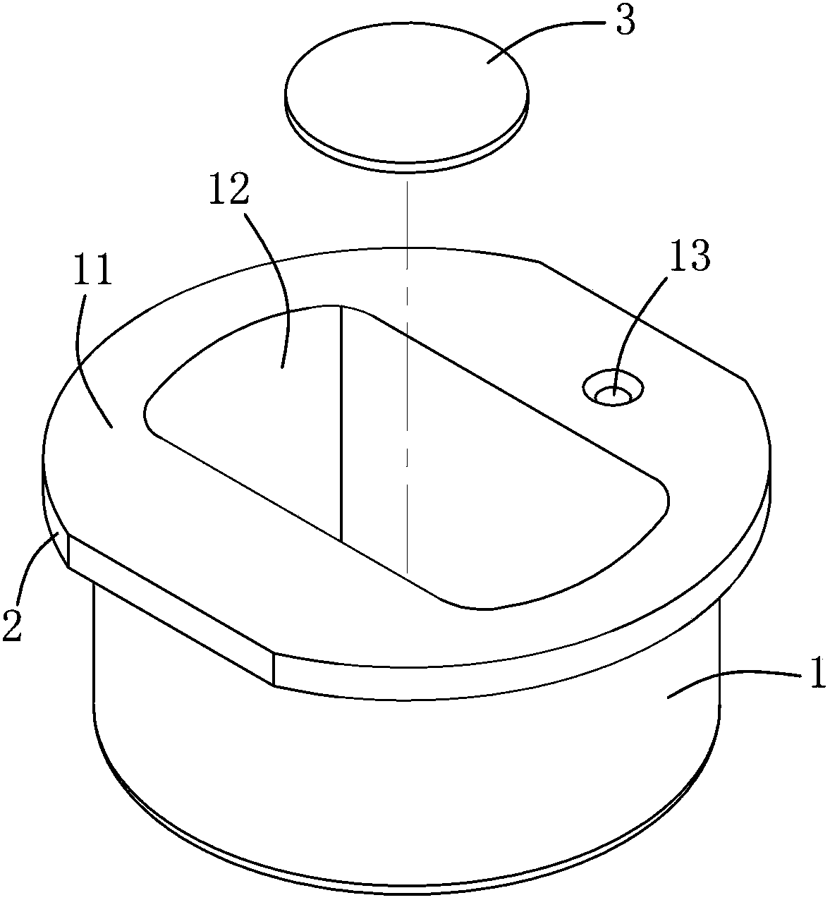
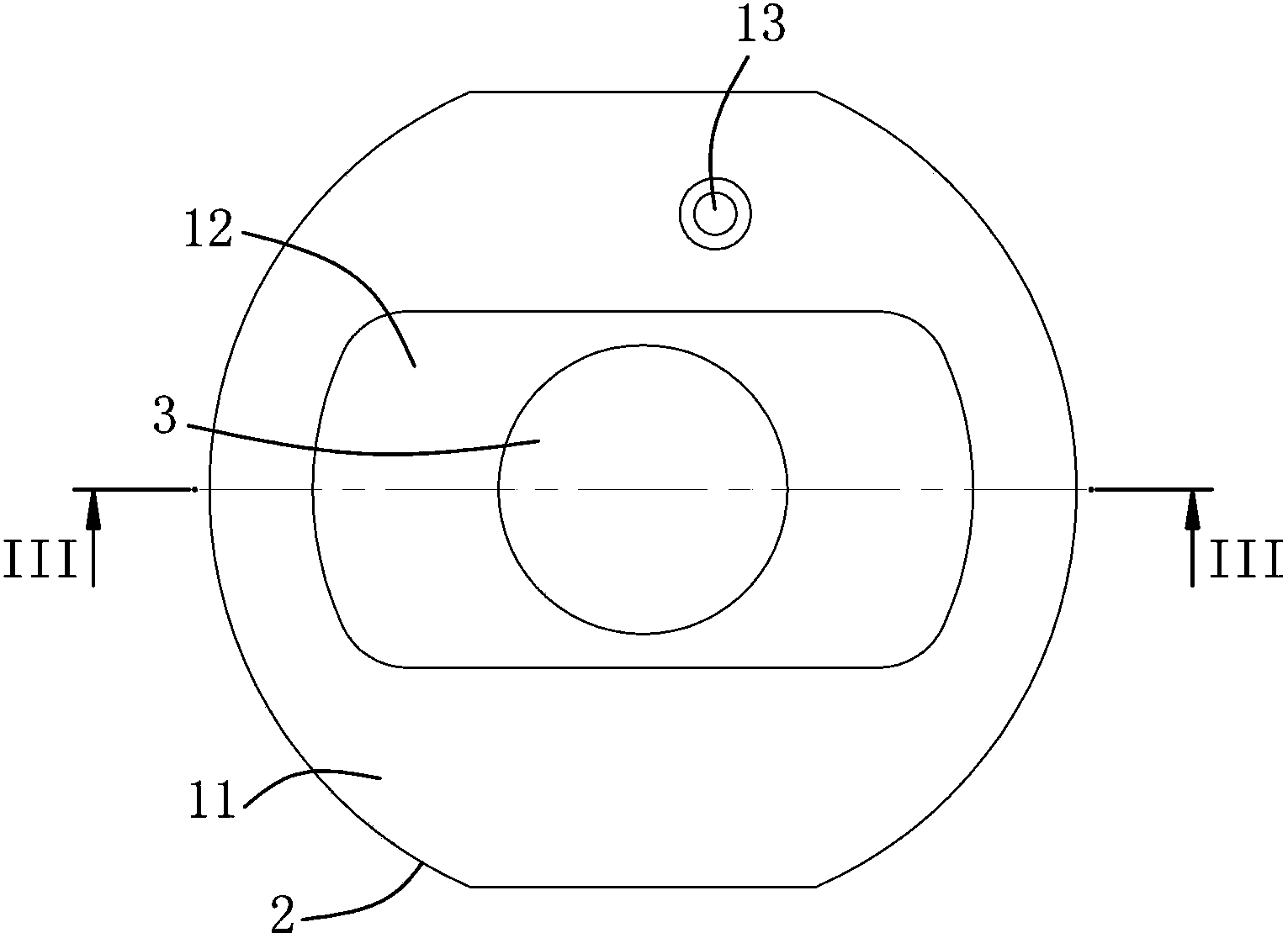
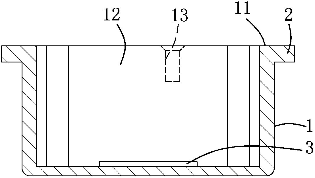
[0016] refer to figure 1 , figure 2 and image 3 , a preferred embodiment of the sensor housing of the present invention is suitable for setting a piezoelectric film 3 , this preferred embodiment includes a housing body 1 and a positioning protrusion 2 .

[0017] The shell body 1 has a top surface 11 , a cavity 12 formed by indentation of the top surface 11 , and a hole 13 formed by indentation of the top surface 11 for inserting a pin. The piezoelectric film 3 is disposed in the chamber 12 . After the pins are inserted into the holes 12, they can be electrically connected to the piezoelectric sheet 3 through the housing 1, thus saving steps during assembly.

[0018] The positioning protrusion 2 protrudes radially from the shell body 1 along the peri...


PUM

PropertyMeasurementUnit
elongationaaaaaaaaaa

Abstract

A sensor shell comprises a shell body. The shell body is provided with a top surface and an accommodating chamber formed by depressing the top surface. A piezoelectric plate is arranged in the accommodating chamber. The sensor shell is mainly made of an aluminum alloy which contains, by weight, 4.5-6% of magnesium, about 0.4% of ferrum, about 0.3% of silicon, about 0.1% of copper, about 0.1% of zinc, 0.05-0.2% of manganese and 0.05-0.2% of chromium, with the balance being aluminum.

Description

technical field [0001] The invention relates to a housing, in particular to a sensor housing. Background technique [0002] The general ultrasonic sensor is made of aluminum sensor housing, but the mechanical properties of aluminum limit the efficiency of the sensor to convert electrical energy into kinetic energy, and may also affect the efficacy of the sensor due to the aftershock of the sensor housing made of aluminum. [0003] In addition, color paint is sprayed on the sensor case for aesthetics, but the paint is not easy to adhere to the smooth surface after metal processing. Generally, the sensor case is energized to make the powder that the paint is easy to adhere to adsorb on the sensor case, and then the paint is applied to the area where the powder adheres to the sensor case. In addition, US Patent No. 20120113758A1 discloses a treatment method. First, a very thin film is coated on the surface of the sensor housing by a wet chemical surface treatment method, and t...

Claims


Application Information

Patent Timeline
Patent Type & Authority Applications(China)
IPC IPC(8): G01D11/24
Inventor 李士丰蔡子勤
Owner TUNG THIH ELECTRONICS
Why Eureka
Try Eureka