3D interaction-type projection lens
A projection lens and interactive technology, applied in the field of projection lenses, can solve problems such as large distortion, unfavorable miniaturization, and lengthening of the projection lens, and achieve the effect of improving optical performance, excellent resolution, and large field of view
- Summary
- Abstract
- Description
- Claims
- Application Information
AI Technical Summary
Problems solved by technology
Method used
Image

Examples
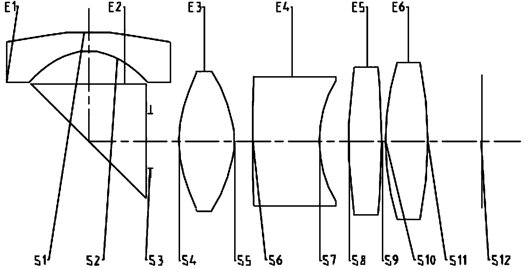
Embodiment 1
[0062] In Example 1, the parameters are as follows: TTL=13.06; f1=-2.455; f2=2.609; f3=-3.410; f4=5.544; f5=5.362; f=1.588;
[0063] ImgH / D=0.624;
[0064] f3 / f=-2.147;
[0065] System parameters: 1 / 6" photosensitive device aperture value 1.8
[0066] Table 1
[0067] surface type
[0068] The following table is the aspheric high-order coefficients A4, A6, A8, A10, A12 of the aspheric lens:
[0069] Table 2
[0070] A4
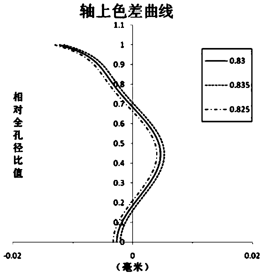
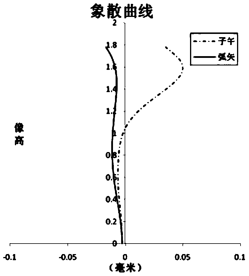
[0071] Figure 2 to Figure 5 The axial chromatic aberration diagram, astigmatism diagram, distortion diagram, and magnification chromatic aberration diagram in Embodiment 1 are shown respectively, and the optical effect in Embodiment 1 can be seen from the diagrams.
Embodiment 2
[0074] In Example 2, the parameters are as follows: TTL=12.756; f1=-2.473; f2=2.546; f3=-3.789; f4=6.247; f5=5.362; f=1.588;
[0075] ImgH / D=0.623;
[0076] f3 / f=-2.386;
[0077] System parameters: 1 / 6" photosensitive device aperture value 1.8
[0078] table 3
[0079] surface type
[0080] The following table is the aspheric high-order coefficients A4, A6, A8, A10, A12 of the aspheric lens:
[0081] Table 4
[0082] A4
[0083] Figure 7 to Figure 10 The axial chromatic aberration diagram, astigmatism diagram, distortion diagram, and magnification chromatic aberration diagram in Embodiment 2 are shown respectively, and the optical effect in Embodiment 2 can be seen from the diagrams.
Embodiment 3
[0086] In Example 3, the parameters are as follows: TTL=13.54; f1=-2.330; f2=2.752; f3=-4.790; f4=7.467; f5=5.362; f=1.588;
[0087] ImgH / D=0.619;
[0088] f3 / f=-3.016;
[0089] System parameters: 1 / 6" photosensitive device aperture value 1.8
[0090] table 5
[0091] surface type
[0092] The following table is the aspheric high-order coefficients A4, A6, A8, A10, A12 of the aspheric lens:
[0093] Table 6
[0094] A4
[0095] Figure 12 to Figure 15 The axial chromatic aberration diagram, astigmatism diagram, distortion diagram, and magnification chromatic aberration diagram in Embodiment 3 are shown respectively, and the optical effect in Embodiment 3 can be seen from the diagrams.
PUM
 Abstract
Description
Claims
Application Information