Light-source optimization method adopting compressed sensing technology

A light source optimization and compressed sensing technology, applied in microlithography exposure equipment, photolithography process exposure devices, etc., can solve problems such as unfavorable improvement of lithography imaging contrast, unfavorable manufacturing, complex light source patterns, etc.

Active Publication Date: 2014-07-02
BEIJING INSTITUTE OF TECHNOLOGYGY
View PDF5 Cites 11 Cited by
  • Summary
  • Abstract
  • Description
  • Claims
  • Application Information

AI Technical Summary

Problems solved by technology

However, the above method has the following four deficiencies: first, the accuracy of the SO optimization result obtained by the above method will decrease significantly with the decrease of the number of observation points at the wafer, so it is impossible to reduce the computational complexity by reducing the number of observation points, thus This limits the improvement of the operational efficiency of the algorithm; second, the light source graphics optimized by the above method are relatively complex, which is not conducive to manufacturing; third, the above method constructs the SO optimization objective function as a quadratic function of the difference between the spatial image and the target graphics, Therefore, it is not conducive to improving the optimized lithography imaging contrast, and at the same time, it cannot fully expand the process window of the lithography system; fourth, the above SO method is based on the scalar imaging model of the lithography system, so it is not suitable for high NA lithography systems
In summary, the existing SO method needs to be further improved and improved in four aspects: optimization efficiency, light source manufacturability, lithography system process window and simulation accuracy.

Method used


Image

  • Light-source optimization method adopting compressed sensing technology
  • Light-source optimization method adopting compressed sensing technology
  • Light-source optimization method adopting compressed sensing technology

Examples


Embodiment

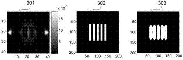
[0148] Such as image 3 Shown is a schematic diagram of the optimized light source pattern, mask pattern and its imaging in the photoresist at the best focal plane under the rated exposure amount obtained by the traditional conjugate gradient method. 301 is an optimized light source pattern obtained by using the traditional conjugate gradient method, white represents the luminous area, black represents the non-luminous area, and the optimization time is 1.73 seconds. 302 is the mask pattern used in the simulation, which is also the target pattern, white represents the opening area, black represents the light blocking area, and its critical dimension is 45nm. Since the present invention relates to a light source optimization method, the mask pattern remains unchanged during the light source optimization process. 303 is to use 301 as the light source and 302 as the mask. When the exposure amount change and the defocus effect are not considered, the image is formed in the photor...


PUM


Abstract

The invention provides a light-source optimization method adopting a compressed sensing technology. The light-source optimization method comprises the following steps: firstly selecting a group of standard orthogonal basis and enabling a light-source graphic to be sparse on the standard orthogonal basis; then expanding the light-source graphic on the standard orthogonal basis to obtain coefficient vector theta and constructing the SO optimization problem into an image restoration problem of solving a minimum L1 norm of theta under the linear-limitation condition, wherein the linear-limitation condition is as follows: imaging in photoresist on a plurality of observation points set at a wafer is consistent to a target graphic. Compared with the traditional SO algorithm adopting the conjugate gradient method, the SO method has the advantages that the operation efficiency can be more effectively improved, and the manufacturability of the optimized light source and a process window of a photoetching system can be improved; simultaneously, a vector imaging model is adopted for describing the imaging process of the photoetching system, the optimized light source not only is applicable to the condition of small NA, but also is applicable to the condition that NA is more than 0.6, and meets the requirement for the simulation precision of high-NA immersed type photoetching system.

Description

technical field [0001] The invention relates to a light source optimization method using compressed sensing technology, and belongs to the technical field of lithographic resolution enhancement. Background technique [0002] The current large-scale integrated circuits are generally manufactured using photolithography systems. The lithography system mainly includes four parts: illumination system (including light source and condenser), mask, projection system and wafer. The light emitted by the light source is focused by the condenser and then enters the mask, and the opening part of the mask transmits light; after passing through the mask, the light is incident on the wafer coated with photoresist through the projection system, so that the mask pattern is copied on the wafer. [0003] The current mainstream lithography system is the 193nm ArF deep ultraviolet lithography system. As the lithography technology node enters 45nm-22nm, the critical dimension of the circuit has b...

Claims


Application Information

Patent Timeline
Patent Type & Authority Applications(China)
IPC IPC(8): G03F7/20
Inventor 马旭宋之洋高杰李艳秋
Owner BEIJING INSTITUTE OF TECHNOLOGYGY
Why Eureka
Try Eureka