
Shunt trip mechanism of disconnector

A shunt tripping and circuit breaker technology, applied in the direction of protection switch operation/release mechanism, etc., can solve the problems of small tripping force of electronic release, high technical and technological requirements, and many auxiliary parts, etc., and achieves a simple structure. , The effect of high tripping sensitivity and small number of parts

Active Publication Date: 2014-07-02
黑龙江省一滴水环保科技有限公司
View PDF6 Cites 1 Cited by
  • Summary
  • Abstract
  • Description
  • Claims
  • Application Information

AI Technical Summary

Problems solved by technology

[0003] The existing circuit breakers mainly use electromagnetic trippers and electronic trippers. The disadvantages of electromagnetic trippers are: high technical and process requirements, many auxiliary parts of the mechanism, and complex structure; another electronic tripper The tripping force of the release is small, and the tripping stroke is small

Method used


Image

  • Shunt trip mechanism of disconnector
  • Shunt trip mechanism of disconnector
  • Shunt trip mechanism of disconnector

Examples


Embodiment

[0032] Embodiment: A shunt tripping mechanism of a circuit breaker

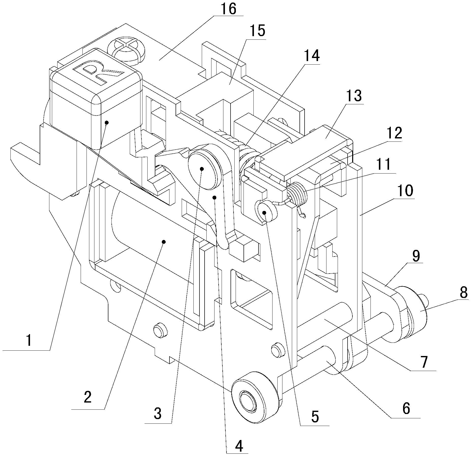
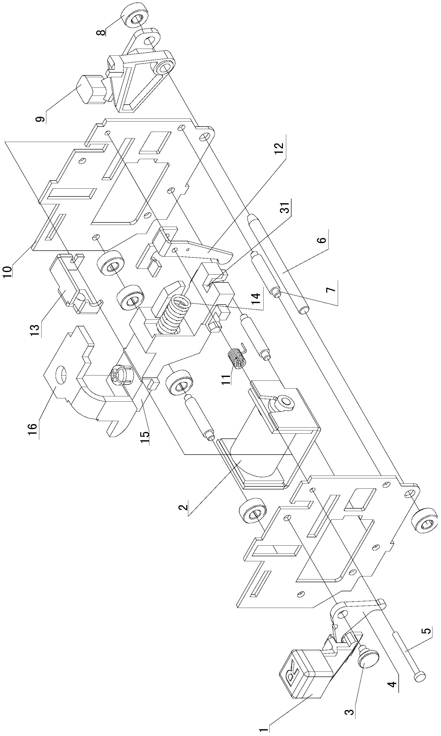
[0033] See attached figure 1 ~ attached Figure 9 As shown, a shunt tripping mechanism of a circuit breaker includes a mounting structure, a reset mechanism, a transmission mechanism and a shunt coil;

[0034] The installation structure includes a pair of parallel and spaced installation plates 10, and the two installation plates 10 are fixedly arranged by three installation plate fixing rods 7. There is a certain structure between the two installation plates 10, and the transmission mechanism and the shunt coil are set. Between the two mounting plates 10. The reset mechanism is arranged on one side of the installation structure.

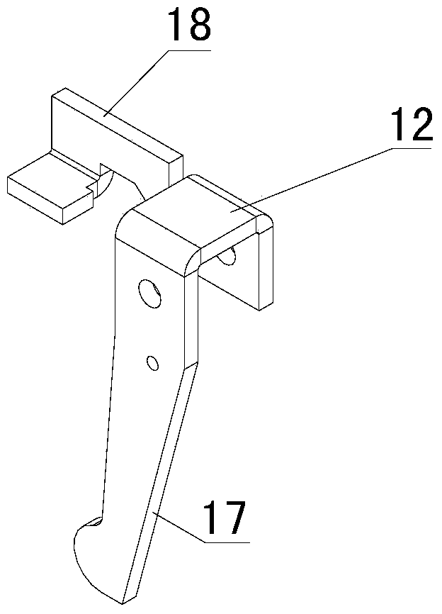
[0035] The reset mechanism includes a reset button 1, a reset link 4, and the reset link 4 includes a reset link fixing part 25, a reset button reset link linkage part 26 and a reset link push rod linkage part 27, and the reset link 4 is rotatably supported on the outside of th...


PUM


Abstract

A shunt trip mechanism of a disconnector comprises a reset button, a reset connecting rod, a pair of mounting plates which are arranged in a spaced mode in parallel, a push rod mounted between the mounting plates, a lock catch, a reset spring, a shunt excitation coil and the like. The push rod, the lock catch and the shunt excitation coil are arranged between the two mounting plates. The reset spring provides stored energy, the shunt excitation coil enables the lock catch and the push rod to be tripped after working, the stored energy is released, the push rod moves, then the push rod is reset through the rest button and the reset connecting rod, and the spring stores energy. The shunt trip mechanism of the disconnector is simple in structure, convenient to assemble, and capable of better lowering cost due to the fact that the shunt excitation coil is changed to be of an electronic type from an electromagnetic type.

Description

technical field [0001] The invention relates to a shunt tripping mechanism of a circuit breaker, belonging to the technical field of electric switches. Background technique [0002] The circuit breaker is used for making, breaking and carrying the rated working current in the circuit, and can provide reliable protection in the case of overload, short circuit and undervoltage of the circuit. A circuit breaker is generally composed of a release, a contact system, an arc extinguishing device, a transmission mechanism and a casing, etc. The release includes an electromagnetic release, a thermal release, an undervoltage release and a shunt release. buckle. The shunt release is used for remote operation of the circuit breaker for opening control. Its electromagnetic coil is connected in parallel to the power supply side of the low-voltage circuit breaker. When opening operation is required, press the normally open button to energize the electromagnet of the shunt release The arm...

Claims


Application Information

Patent Timeline
IPC IPC(8): H01H71/24H01H71/58
Inventor 曾莹张勇
Owner 黑龙江省一滴水环保科技有限公司
Learn More