
A method for manufacturing the whole hole of steel main girder of large composite beam

A manufacturing method and technology for steel main beams, which are applied in the directions of bridges, bridge materials, bridge construction, etc., can solve the problems of increasing the difficulty of controlling the alignment of steel beams, prolonging the construction period, increasing the manufacturing cost, etc., and achieving the control of the manufacturing alignment and the manufacturing accuracy. , Reduce the hidden dangers of safety, and make the line shape easy to control.

Active Publication Date: 2016-09-07
CHINA RAILWAY BAOJI BRIDGE GRP
View PDF5 Cites 0 Cited by
  • Summary
  • Abstract
  • Description
  • Claims
  • Application Information

AI Technical Summary

Problems solved by technology

During the implementation of this method, it is necessary to manufacture two types of assembled tire frames, the small-segment steel beam and the large-segment steel beam, according to the linear design of the large-scale steel main girder. Purchase and purchase multiple sets of hydraulic jacking equipment, and make secondary adjustments to the manufacturing alignment of large-segment steel beams, resulting in increased difficulty in controlling the alignment of steel beams, greatly increasing manufacturing costs, and prolonging the construction period

Method used


Image

  • A method for manufacturing the whole hole of steel main girder of large composite beam
  • A method for manufacturing the whole hole of steel main girder of large composite beam
  • A method for manufacturing the whole hole of steel main girder of large composite beam

Examples


Embodiment 1

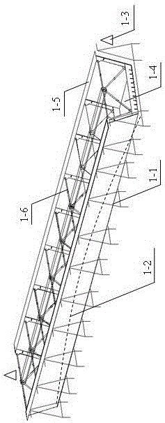
[0011] Embodiment 1: with reference to attached figure 1 . A large-scale combined steel main girder assembly tire frame system, including the steel main beam assembly tire frame and a measurement system, the assembly tire frame 1-1 is composed of a plurality of steel frames arranged vertically in a line, and the linear shape 1-2 constitutes the steel main girder vertical curve, and set the longitudinal measurement reference point 1-3 at the end of the frame.

[0012] figure 1 The overall schematic diagram made for the composite girder steel main girder, 1-1 indicates the total tire frame, which is used to control the outline size of the steel main girder, and 1-2 indicates the vertical alignment of the tire frame, which is used to control the linear arching of the steel main girder , 1-3 represent the longitudinal measurement points, which are used to measure the straightness of the steel girder.

Embodiment 2

[0013] Embodiment 2: A large-scale composite girder steel girder composed of steel components, two steel girder web units 1-5 and one steel girder floor unit 1-4 form a channel-shaped steel girder, and multiple steel girders The three sides of the partition unit 1-6 are respectively welded to the inner wall of the channel-shaped steel main beam to form the steel main beam. The multi-steel girders are welded and connected to form a large-segment steel girder, and the bottom plate units 1-4 of the steel girder are vertical curves.

[0014] 1-4 represent the steel main girder bottom plate unit, 1-5 represent the steel main girder web plate unit, 1-6 represent the steel main girder diaphragm unit; Figure 2 is a schematic diagram of the steel main girder's whole hole manufacturing process, and state 2-1 represents the bottom plate Unit group welding process, state 2-2a represents the manufacturing process of the segmental steel main girder, state 2-2b represents the process of lift...


PUM


Abstract

The invention relates to a novel combination joist steel girder complete hole and a manufacture method thereof. Due to the fact that large-scale steel girder manufacturing precision is high and linear control is difficult, a traditional steel girder combination technology can not meet the manufacturing precision requirements and is large in investment cost. A large-scale steel girder complete hole manufacturing technology is developed, namely a scheme of plate unit - section steel girder - large section steel girder is adopted on an assembling support, and a large-scale steel girder is manufactured through one step on the assembling support. The method has the advantage that limit of a traditional steel girder manufacture technology is broken through, and a method of assembling and welding steel girders on the assembling support sequentially into the large-scale steel girder is adopted; the large-scale steel girder is manufactured through one step on the assembling support, and steel girder manufacturing linear secondary adjustment is avoided; a procedure of transferring small section steel girder in the field is avoided; only a large-scale steel girder field and the assembling support are required, and production field is saved.

Description

technical field [0001] The invention relates to a method for processing and manufacturing a steel main girder of a large composite girder and a whole hole, and belongs to the field of processing and manufacturing of large bridge steel components. Background technique [0002] With the development and progress of transportation science and technology, bridge construction is constantly developing towards "large-scale and assembly-oriented". The control is difficult, and there is an urgent need to develop a new method for processing and manufacturing composite girder steel girders. In the past, the composite girder steel girders all adopted the manufacturing method of "plate element → small segment steel beam → large segment steel beam". During the implementation process of this method, it is necessary to manufacture two types of assembled tire frames, the small-segment steel beam and the large-segment steel beam, according to the production line design of the large-scale stee...

Claims


Application Information

Patent Timeline
Patent Type & Authority Patents(China)
IPC IPC(8): E01D21/00E01D2/00E01D101/30
Inventor 李军平刘治国成宇海车平吴小兵王志翔路玉荣权红烈
Owner CHINA RAILWAY BAOJI BRIDGE GRP
Learn More