Eureka AIR delivers breakthrough ideas for toughest innovation challenges, trusted by R&D personnel around the world.

Test system and method for accurately measuring dielectric constants

A technology of permittivity and test system, applied in the field of electromagnetic parameters, can solve the problems that simultaneous accurate measurement cannot be achieved, the production of test system is cumbersome, and the processing cost is high, and the effect of small error, easy integration and accurate measurement is achieved.

Active Publication Date: 2014-07-09
NANJING UNIV OF INFORMATION SCI & TECH
View PDF6 Cites 21 Cited by
  • Summary
  • Abstract
  • Description
  • Claims
  • Application Information

AI Technical Summary

Problems solved by technology

[0025] According to the above-mentioned several commonly used dielectric constant measurement methods, the existing methods generally can only accurately measure the dielectric constant or high dielectric constant, and cannot achieve simultaneous accurate measurement, and some methods of testing systems or samples The production is relatively cumbersome, the processing cost is high, and it is difficult to make

Method used


Image

  • Test system and method for accurately measuring dielectric constants
  • Test system and method for accurately measuring dielectric constants
  • Test system and method for accurately measuring dielectric constants

Examples


Embodiment Construction

[0062] The technical solutions provided by the present invention will be described in detail below in conjunction with specific examples. It should be understood that the following specific embodiments are only used to illustrate the present invention and are not intended to limit the scope of the present invention.

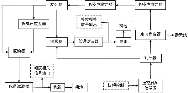
[0063] Such as figure 1 Shown is the schematic diagram of test system in the present invention, as figure 2 Shown is a schematic diagram of a single antenna unit (i.e. microstrip patch antenna) in the present invention, as image 3 Shown is the physical map of the microstrip patch antenna; the present invention provides a test system for accurately measuring the dielectric constant, including a sample, an antenna part, a radio frequency circuit part and a data processing display part; wherein, the antenna part, the radio frequency circuit part, The data processing and display part is connected sequentially, and the antenna part tests the sample; the incident wa...


PUM


Abstract

The invention relates to a test system for accurately measuring dielectric constants. The test system comprises an antenna part, a radio-frequency circuit part and a data processing and displaying part. The antenna part comprises a testing antenna and a scattering sample, the radio-frequency circuit part comprises a radio-frequency signal source and a radio-frequency circuit, and the radio-frequency circuit is composed of a directional coupler, a low noise amplifier, a power divider, a mixer and a low pass filter. The data processing and displaying part is composed of an amplifying circuit and an ARM development board. Electromagnetic parameters of the sample are accurately measured with changes of the input impedance of an antenna and a radiation field. The test system has the advantages that low dielectric constant materials and high dielectric constant materials can be accurately measured, errors are small, the testing system is simple, integration is convenient to achieve, the scattering sample is simple in shape and easy to machine, and sweep testing can be carried out on the scattering sample.

Description

technical field [0001] The invention belongs to the field of microblogging measurement, and in particular relates to a method for accurately measuring the electromagnetic parameters (dielectric constant and loss) of a sample by using the change of antenna input impedance and the radiation field. Background technique [0002] With the development of microwave technology, there are more and more demands for microwave components in the fields of aerospace, military and civilian, digital communication, scientific research, etc., so that microwave materials, microwave dielectric substrates and components are constantly being developed. These materials have been played an increasingly important role. Microwave materials are now used in various microwave products. As people study microwave frequency bands are getting higher and higher, microwave devices are getting smaller and smaller. New materials are constantly inventing and appearing, and the data required by the process is als...

Claims


Application Information

Patent Timeline
IPC IPC(8): G01R27/26
Inventor 文舸一蒋佳佳王峰
Owner NANJING UNIV OF INFORMATION SCI & TECH
Why Eureka
Eureka Blog
Learn More