
Multichannel-scanning-time-delay calculating method and device

A calculation method and technology of a calculation device are applied in the field of multi-channel scanning delay calculation methods and devices, which can solve the problems of inaccurate delay and complex logic implementation, and achieve the effects of accurate delay, simple logic implementation and error reduction.

Inactive Publication Date: 2014-07-09
SHENZHEN LANDWIND IND
View PDF3 Cites 4 Cited by
  • Summary
  • Abstract
  • Description
  • Claims
  • Application Information

AI Technical Summary

Problems solved by technology

[0006] In order to solve the defects of inaccurate delay and complex logic implementation in the prior art, the present invention proposes a multi-channel scanning delay calculation method and device with simple calculation and accurate calculation to improve the imaging quality of the ultrasonic imaging system. The method is suitable for Suitable for three types of probes: linear array, convex array, and phased array, suitable for non-deflection scanning, deflection scanning, and various linear densities

Method used


Image

  • Multichannel-scanning-time-delay calculating method and device
  • Multichannel-scanning-time-delay calculating method and device
  • Multichannel-scanning-time-delay calculating method and device

Examples


Embodiment Construction

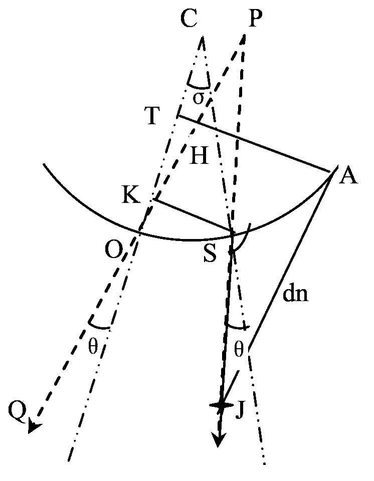
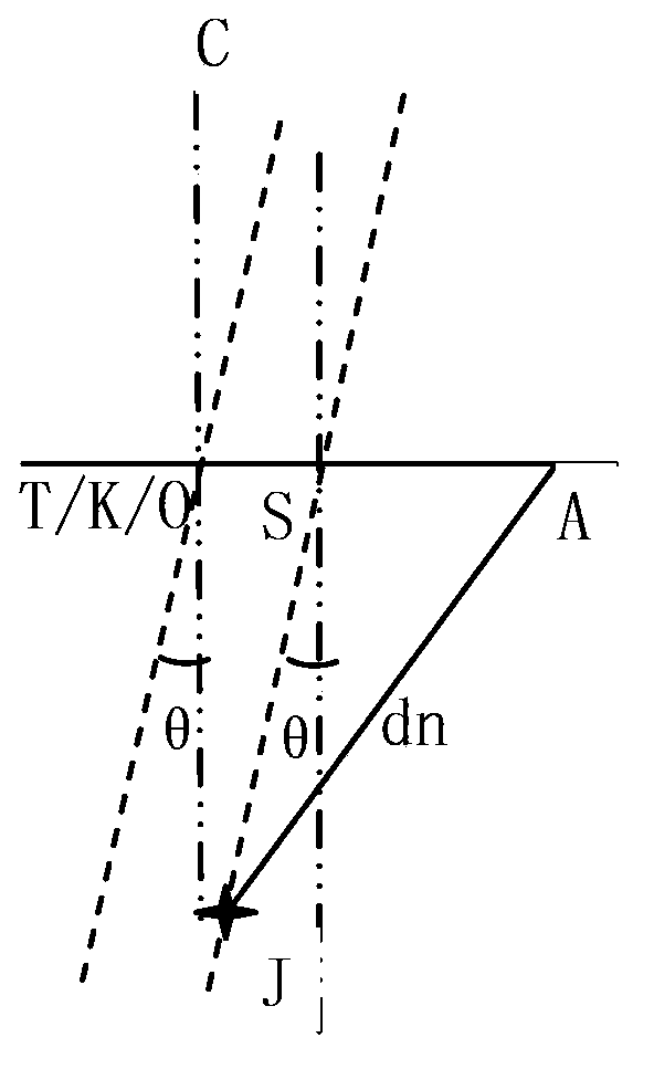
[0031] Figure 1A is the geometric diagram of the delay distance of the convex array, Figure 1B It is a geometrical schematic diagram of the delay distance of a phased array or a linear array. Among them, C is the center of the convex array, O is the coordinate reference point (O point can be any point on the surface of the probe element), OC is the normal line of the probe passing through O, A is the position of a certain array element, and SF is the scanning line , where point S is the starting point of the scan line, J is the focal point or focal point, θ is the angle between the scan line SF and the normal of the probe passing through point S, that is, the deflection angle of the scan line, and σ is the distance between points O and S The included angle of the probe normal. The line segment SK is perpendicular to the line segment OC (ie: SK⊥OC), the line segment AT is also perpendicular to the line segment OC (ie: AT⊥OC), the line segment SK is the vertical distance from...


PUM


Abstract

The invention discloses a multichannel-scanning-time-delay calculating method and device. The method includes the following steps: using any point on an array-element surface as a reference point and calculating position parameters of each array element center point and scanning line start point in channels, relative to the reference point; calculating a distance dn of each array element center point to a focal point on each scanning line; and calculating a quantized delay time tn from the focal point F on each scanning line to each channel. The multichannel-scanning-time-delay calculating method and device improve the focusing precision so that the quality of fundamental-wave images can be improved and artifacts under harmonic waves can be eliminated and real-time operation quantity in time-delay calculation is reduced and thus resources can be saved.

Description

technical field [0001] The invention relates to ultrasonic imaging control technology, in particular to a multi-channel scanning delay calculation method and device. Background technique [0002] Ultrasound imaging is the transmission and reception of multiple channels. In order to improve the signal-to-noise ratio of the signal and the resolution of the imaging, it is necessary to superpose multiple signals in phase, that is, to focus. In a probe array, the spatial distances from the array elements corresponding to each channel to the same focal point are different. To achieve in-phase superposition at the focal point, it is necessary to control the transmitting and receiving signals of each channel accordingly. [0003] In the ultrasonic system, except for the CW scanning mode, ultrasonic waves are transmitted in the form of pulses, and different channels need to be focused with different transmission and reception start times, that is, different delays for different signa...

Claims


Application Information

Patent Timeline
IPC IPC(8): G01S15/89G01S7/52
CPCG01S15/89G01S7/52015
Inventor 李小雪王勇张羽
Owner SHENZHEN LANDWIND IND
Learn More