Novel inductor and manufacturing method thereof

A new type of inductance technology, applied in the manufacture of inductors/transformers/magnets, inductors, fixed inductors, etc., can solve the problems of unreachable, structural design layout and material collocation restrictions, etc., to improve firmness, reduce quality risks, cost saving effect

Inactive Publication Date: 2014-07-09
深圳市科达嘉电子有限公司
View PDF8 Cites 65 Cited by
  • Summary
  • Abstract
  • Description
  • Claims
  • Application Information

AI Technical Summary

Problems solved by technology

Among the new one-piece die-casting inductors currently on the market, due to the limitations of structural design layout and material matching, the above effects cannot be achieved.

Method used


Image

  • Novel inductor and manufacturing method thereof
  • Novel inductor and manufacturing method thereof
  • Novel inductor and manufacturing method thereof

Examples


Embodiment Construction

[0061] The novel inductor of the present invention and its manufacturing method will be further described in detail below in conjunction with the accompanying drawings.

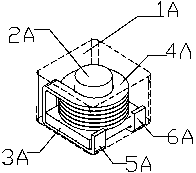
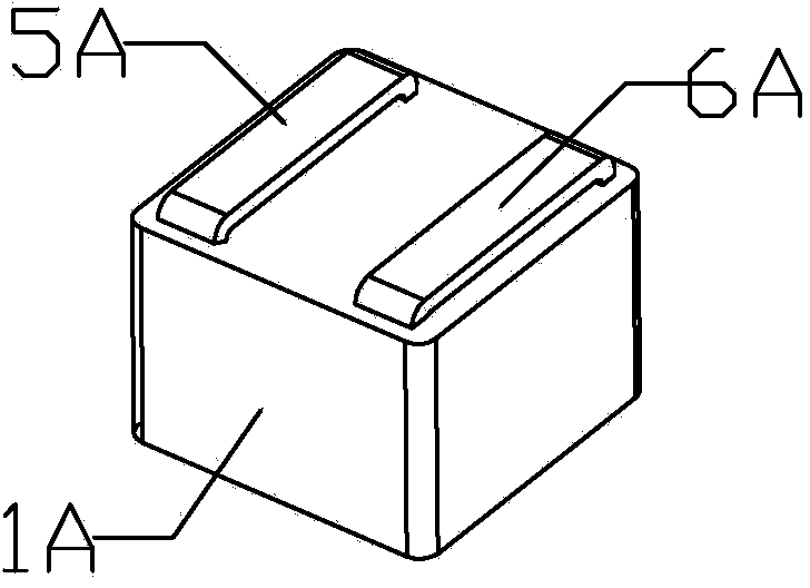
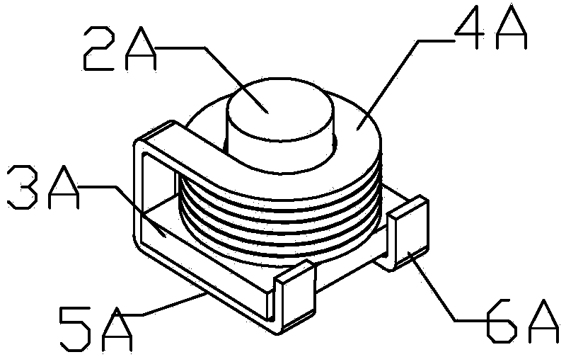
[0062] Such as Figure 1 to Figure 28 As shown, the present invention is a new type of inductor, which is characterized in that: the new type of inductor includes enameled coils (4A, 4B, 4C) and mandrels (2A, 2B, 2C, 3A, 3B, 3C) made into inlaid inner core( image 3 , Figure 10 , Figure 20 ); the pre-fabricated inlay core ( image 3 , Figure 10 , Figure 20 ), put into the corresponding mold, and make sure that the terminals or coils connected to the coils are extended to form electrodes (5A, 5B, 6A, 6B, ) or pre-plated to form electrodes (5C, 5D, 5E, 5F, 6C, 6D , 6E, 6F) are partly exposed; through a mechanical or hydraulic powder metallurgy molding press, the metal powder is die-cast to form an outer cladding layer (1A, 1B, 1C); the mosaic inner core ( image 3 , Figure 10 , Figure 20 ) and el...


PUM


Abstract

The invention discloses a novel inductor. The novel inductor is characterized by comprising an inset inner core, an electrode and an outer wrapping layer, the inset inner core comprises an enameled coil and a mandrel, and the inset inner core and the electrode are buried in the center of the outer wrapping layer. The novel inductor has the advantages that manufacturability and performance are improved.

Description

technical field [0001] The invention relates to a novel inductor and a manufacturing method thereof, in particular to a novel inductor capable of improving manufacturability and performance and a manufacturing method thereof. Background technique [0002] With the continuous innovation of electronic technology, the requirements for high-efficiency and low-loss electronic components continue to increase. Among the new one-piece die-casting inductors currently on the market, due to the limitations of structural design layout and material matching, the above effects cannot be achieved. Therefore, there is a need for an improved inductive component and method of manufacturing the same that overcomes the foregoing limitations, provides capabilities, features, and functions that are not available in current manufacturing equipment and methods, and a new type of inductor for a specific application field. Contents of the invention [0003] The object of the present invention is t...

Claims


Application Information

Patent Timeline
Patent Type & Authority Applications(China)
IPC IPC(8): H01F17/04H01F27/28H01F27/24H01F1/147H01F27/29H01F41/00
CPCH01F3/08H01F17/045H01F27/022H01F27/292H01F41/005H01F41/0246H01F2003/106H01F2017/046H01F2017/048H01F41/076H01F27/2847H01F27/2852H01F27/306G01F3/08
Inventor 黄伟嫦
Owner 深圳市科达嘉电子有限公司
Why Eureka
Try Eureka