
Full-automatic optical fiber insertion loss and return loss test instrument and method

A return loss test and insertion return loss technology, applied in electromagnetic wave transmission systems, electrical components, transmission systems, etc., can solve problems such as fiber damage and low test efficiency

Inactive Publication Date: 2014-07-09
OFT OPTOELECTRONICS TECH
View PDF3 Cites 7 Cited by
  • Summary
  • Abstract
  • Description
  • Claims
  • Application Information

AI Technical Summary

Problems solved by technology

At present, when the insertion loss and return loss testers on the market test the return loss of optical fiber connectors, they need to wind the optical fiber to eliminate the influence of light reflection on the rear end of the optical fiber connector, which is easy to cause damage to the optical fiber during the test process. Moreover, only one wavelength of data can be tested at a time during the test, and the test efficiency is relatively low.

Method used


Image

  • Full-automatic optical fiber insertion loss and return loss test instrument and method

Examples


Embodiment Construction

[0019] The fully automatic optical insertion return loss tester and test method of the present invention will be further described in detail below in conjunction with the accompanying drawings and specific implementation methods.

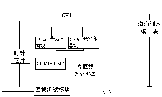
[0020] As shown in the figure, the automatic optical insertion return loss tester of the present invention includes a central processing unit (CPU), and the central processing unit is respectively connected to a wavelength division multiplexer (WDM) through a 1310nm optical emission module and a 1550nm optical emission module. ;The output end of the wavelength division multiplexer signal is connected to the splitter (high return loss optical splitter), and the output end of the high return loss optical splitter is connected to the front end of the jumper under test through the FC / APC connector and the test line On the surface, the return loss signal end of the high return loss optical splitter is connected to the return loss test module; the return l...


PUM


Abstract

The invention discloses a full-automatic optical fiber insertion loss and return loss test instrument and method. The full-automatic optical fiber insertion loss and return loss test instrument comprises a central processing unit and further comprises a clock chip which can provide the time reference. The central processing unit is connected with a wavelength division multiplexer through a 1310 nm light transmitting module and a 1550 nm light transmitting module. The signal output end of the wavelength division multiplexer is connected with an optical divider, wherein the output end of the optical divider is connected to the front end face of a tested wire jumper, and the return loss signal end of the optical divider is connected with a return loss test module which is in information transmission with the central processing unit. The clock chip is connected with the return loss test module and the central processing unit and provides the reference time for the return loss test module and the central processing unit. After the full-automatic optical fiber insertion loss and return loss test instrument and method are adopted, the aim of simultaneously testing optical performance of an optical fiber patch cord on the wavelength of 1310 nm and the wavelength of 1550 nm. Reflection values of different end faces can be distinguished, the aim of preventing optical fiber winding is achieved, test is convenient and reliable, optical fibers can be prevented from damage in the test process, and product test efficiency is greatly improved.

Description

[0001] technical field [0002] The invention relates to a device for testing optical fiber connectors, in particular to a fully automatic optical insertion return loss tester and a testing method, belonging to the technical field of optical fiber communication. Background technique [0003] Optical fiber communication has many advantages such as stable signal, low loss, long transmission distance and high capacity, and has been widely used in the construction of modern communication networks in various countries. At present, my country's optical fiber communication network is being built rapidly, and the three major operators and broadcasting and television systems have all determined the idea of ​​"accelerating the entry of light into copper and retreating from copper, and promoting the strategic transformation of access networks". Optical fiber active connectors, like optical fibers, are the most basic components of optical fiber communication networks, and have a huge d...

Claims


Application Information

Patent Timeline
Patent Type & Authority Applications(China)
IPC IPC(8): H04B10/071
Inventor 周永军
Owner OFT OPTOELECTRONICS TECH
Learn More