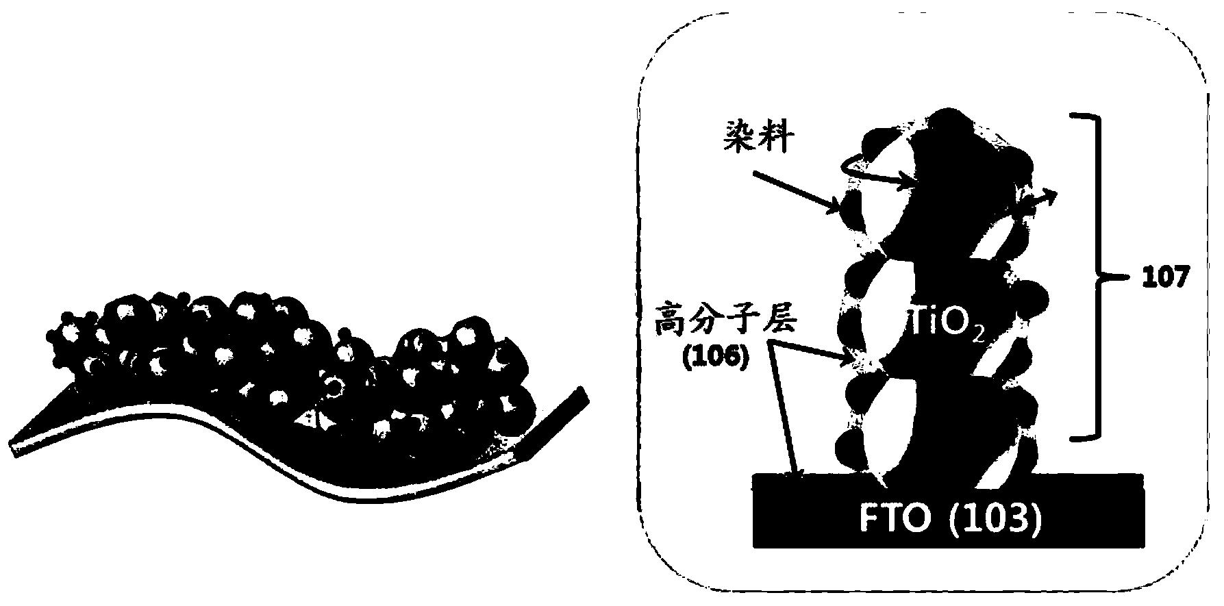
Photoelectrode for a dye-sensitized solar cell, method for manufacturing the photoelectrode, and dye-sensitized solar cell using the photoelectrode
A solar cell and dye-sensitized technology, applied in the field of photoelectrode for dye-sensitized solar cell and its manufacture, and the field of dye-sensitized solar cell using the photoelectrode, which can solve the problem of structural damage of photosensitive material and easy generation of cracks , Electrode peeling and other problems, to achieve excellent durability, enhance adhesion, and maintain the effect of electrical characteristics
- Summary
- Abstract
- Description
- Claims
- Application Information
AI Technical Summary
Problems solved by technology
Method used
Image
Examples
Embodiment 1
[0127] (manufacturing of photoelectrodes)
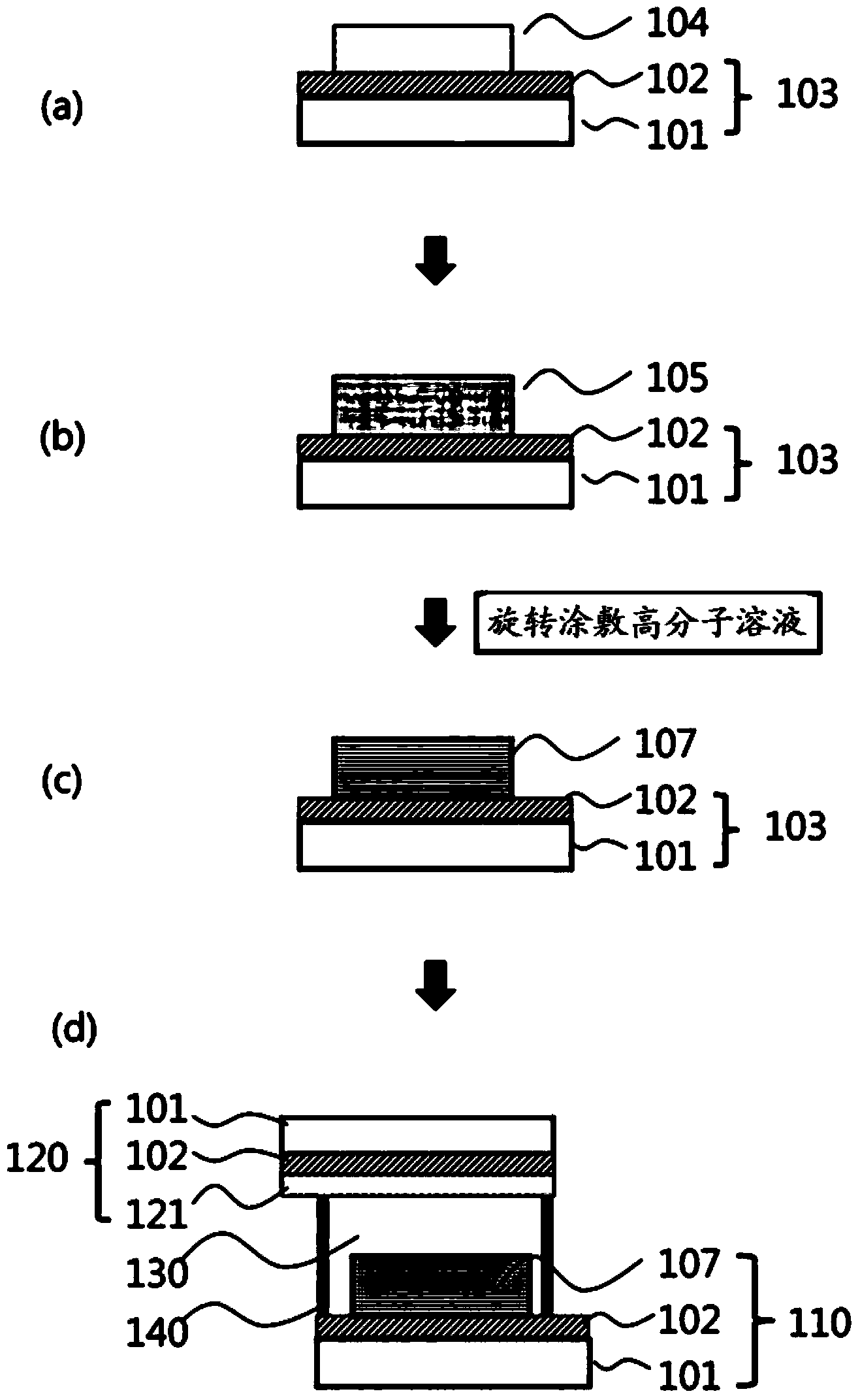
[0128] Prepare a conductive glass substrate (Philkington company, material: conductive glass (FTO), thickness 2.2cm, 8Ω / sq, image 3 including substrates 101 and 102).
[0129] After that, metal oxide nanoparticles containing 18.5 wt% of titanium oxide nanoparticles (average particle size: 20nm), 0.05 wt% of binder polymer (ethyl cellulose) and the balance of solvent (Terpineol) After the slurry was coated on the glass substrate (using doctor blade coating method), the substrate was heat-treated at a temperature of 500° C. for 30 minutes, thereby forming a porous film including metal oxide nanoparticles ( Thickness: 10 μm). Next, the composite electrode was impregnated with 0.5 mM ruthenium (Ru) photosensitive dye N719 (bis(tetrabutylammonium)-cis-(dithiocyano-N,N'-bis(4-carboxylic acid) Base-4'-carboxylic acid-2,2'-bipyridine)ruthenium(II), bis(tetrabutylammonium)-cis-(dithiocyanato-N,N'-bis(4-carboxylato-4'-carboxylic acid-2, 2...
Embodiment 2
[0136] (manufacturing of photoelectrodes)
[0137] Prepare a conductive glass substrate (Philkington company, material FTO, thickness 2.2cm, 8Ω / sq, image 3 including substrates 101 and 102).
[0138] After that, metal oxide nanoparticles containing 18.5 wt% of titanium oxide nanoparticles (average particle size: 20nm), 0.05 wt% of binder polymer (ethyl cellulose) and the balance of solvent (Terpineol) After the slurry was coated on the glass substrate (by the doctor blade method), the substrate was subjected to heat treatment at a temperature of 500° C. for 30 minutes, thereby forming a porous film (thickness: 10 μm) including metal oxide nanoparticles . Next, the composite electrode was impregnated with 0.5 mM ruthenium (Ru) photosensitive dye N719 (bis(tetrabutylammonium)-cis-(dithiocyano-N,N'-bis(4-carboxylic acid) Base-4'-carboxylic acid-2,2'-bipyridine)ruthenium(II), bis(tetrabutylammonium)-cis-(dithiocyanato-N,N'-bis(4-carboxylato-4'-carboxylic acid-2, 2'-bipyridine...
Embodiment 3
[0145] (manufacturing of photoelectrodes)
[0146] Prepare a conductive glass substrate (Philkington company, material FTO, thickness 2.2cm, 8Ω / sq, image 3 including substrates 101 and 102).
[0147] After that, metal oxide nanoparticles containing 18.5 wt% of titanium oxide nanoparticles (average particle size: 20nm), 0.05 wt% of binder polymer (ethyl cellulose) and the balance of solvent (Terpineol) After the slurry was coated on the glass substrate (by the doctor blade method), the substrate was heat-treated at a temperature of 500° C. for 30 minutes, thereby forming a porous film (thickness: 10 μm) including metal oxide nanoparticles . Next, the composite electrode was impregnated with 0.5 mM ruthenium (Ru) photosensitive dye N719 (bis(tetrabutylammonium)-cis-(dithiocyano-N,N'-bis(4-carboxylic acid) Base-4'-carboxylic acid-2,2'-bipyridine)ruthenium(II), bis(tetrabutylammonium)-cis-(dithiocyanato-N,N'-bis(4-carboxylato-4'-carboxylic acid-2, 2'-bipyridine) ruthenium (II...
PUM
| Property | Measurement | Unit |
|---|---|---|
| diameter | aaaaa | aaaaa |
| thickness | aaaaa | aaaaa |
| thickness | aaaaa | aaaaa |
Abstract
Description
Claims
Application Information
 - R&D
- Intellectual Property
- Life Sciences
- Materials
- Tech Scout
- Unparalleled Data Quality
- Higher Quality Content
- 60% Fewer Hallucinations
Browse by: Latest US Patents, China's latest patents, Technical Efficacy Thesaurus, Application Domain, Technology Topic, Popular Technical Reports.
© 2025 PatSnap. All rights reserved.Legal|Privacy policy|Modern Slavery Act Transparency Statement|Sitemap|About US| Contact US: help@patsnap.com


