
Magnetic suspension drainage device

A magnetic and drainage tube technology, applied in the direction of suction devices, hypodermic injection devices, catheters, etc., can solve the problems of falling off, unable to be inserted, easy to fall off, etc., and achieve good traction resistance, convenient replacement, and not easy to fall off.

Inactive Publication Date: 2014-07-16
尚楠
View PDF7 Cites 2 Cited by
  • Summary
  • Abstract
  • Description
  • Claims
  • Application Information

AI Technical Summary

Problems solved by technology

But the drainage tube currently used is a single J tube, which has the following problems: the first is that it is too long, because the front end of the single J tube has elastic bending, which changes the characteristics of the ureter itself of the normal anatomical structure, resulting in the placement of the long drainage tube. It is extremely inconvenient for doctors to insert or replace, and it is often impossible to insert in clinical practice.
If a patient who relies on single J tube drainage accidentally falls off the single J tube at home, he must rush to the hospital for reinsertion in time, otherwise it will easily lead to failure to reinsert
The second is that it is easy to fall off, because the single J tube is only stuck in the junction of the renal pelvis and ureter, which is the first stenosis of the ureter, by the elastic bending of the front end, and it can move or even fall off with a little external force
Once the single J tube is pulled out, it must be strictly disinfected when it is reset, and the operation cannot be standardized at the patient's home, which increases the risk of infection

Method used


Image

  • Magnetic suspension drainage device
  • Magnetic suspension drainage device
  • Magnetic suspension drainage device

Examples


Embodiment Construction

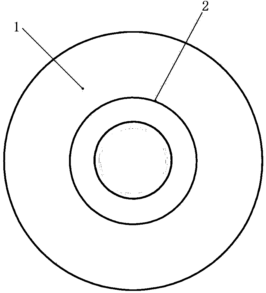
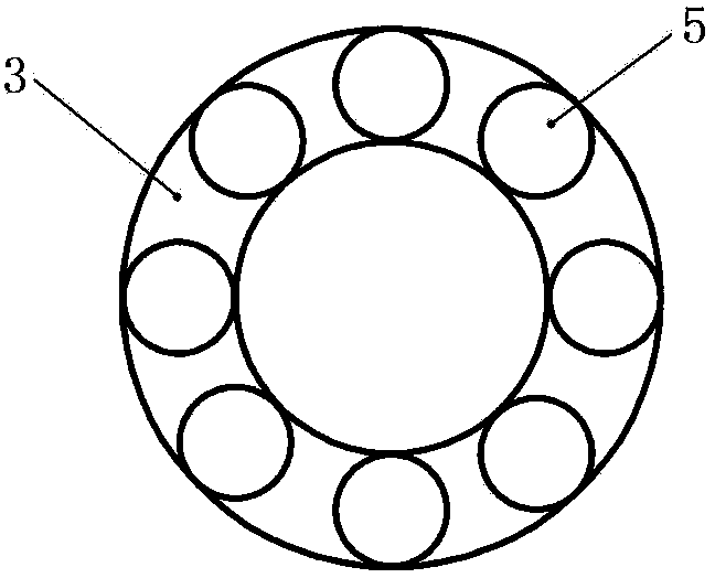
[0015] refer to figure 1 and figure 2 , which includes a drainage tube fixing ring and a drainage tube; the drainage tube fixing ring includes a drainage tube fixing ring body 1, and a strong magnetic ring 2 is embedded in the drainage tube fixing ring; the drainage tube includes a tube body 3, A strong magnetic ring 4 is buried in the middle of the body;

[0016] When performing skin stoma surgery, the drainage tube fixing ring is buried in the subcutaneous or muscle layer of the human body, the drainage tube is inserted into the ureter, and the drainage tube and the drainage tube are connected by the strong magnetic ring on the drainage tube and the strong magnetic ring on the drainage tube fixing ring. The drainage tube fixing ring is adsorbed together;

[0017] refer to figure 1 and image 3 , it includes a drainage tube fixing ring and a drainage tube; the drainage tube fixing ring includes a drainage tube fixing ring body 1, and a strong magnetic ring 2 is embedded ...


PUM


Abstract

The invention discloses a magnetic suspension drainage device, and relates to the field of medical instruments. The magnetic suspension drainage device is designed for mainly solving the problem that a drainage tube in use at present is inconvenient for a physician to put in or replace and prone to falling off. The magnetic suspension drainage device comprises a drainage tube fixing ring and a drainage tube, wherein the drainage tube fixing ring comprises a drainage tube fixing ring body, and a strong magnetic ring is buried in the drainage tube fixing ring body; the drainage tube comprises a tube body, and a strong magnetic ring is buried in the middle of the tube body; it is also allowed that a plurality of magnet sections are buried between the two layers of tube walls in the middle of the drainage tube body along the circumferences of the tube walls. A strong magnetic resisting device comprises a shell, a hole for the drainage tube to stretch in is formed in the shell, and a strong magnetic ring is buried in the circumference around the hole in the shell. The strong magnetic resisting device comprises a handle and a strong magnet which are connected together through a flexible push rod, and the diameter of the strong magnet is smaller than the diameter of the drainage tube. The magnetic suspension drainage device has the advantages of being convenient to put in and replace and not prone to falling off.

Description

Technical field: [0001] The invention relates to the field of medical instruments. Background technique: [0002] After ureterostomy, in order to prevent ureteral atresia at the skin stoma, a drainage tube needs to be placed, that is, one end of the drainage tube is placed in the renal pelvis, and the other end goes antegrade along the ureter to the outside of the body. But the drainage tube currently used is a single J tube, which has the following problems: the first is that it is too long, because the front end of the single J tube has elastic bending, which changes the characteristics of the ureter itself of the normal anatomical structure, resulting in the placement of the long drainage tube. It is extremely inconvenient for doctors to insert or replace, and clinically, it is often impossible to insert. If a patient who relies on single J tube drainage accidentally drops the single J tube at home, he must rush to the hospital for reinsertion in time, otherwise it will ...

Claims


Application Information

Patent Timeline
Patent Type & Authority Applications(China)
IPC IPC(8): A61M1/00A61M25/04
CPCA61M1/84
Inventor 尚楠
Owner 尚楠
Learn More