Steel pipe cleaning device

A technology for cleaning devices and steel pipes, which is applied to workpiece cleaning devices, cleaning hollow objects, cleaning methods, and utensils. It can solve the problems of lack of cleaning, complex overall structure, and damage to workers' limbs, and achieve strong cleaning power and guarantee cleaning. The effect of quality, simplification of structure

Inactive Publication Date: 2014-07-16
CHANGSHU WATER SUPPLY & SEWERAGE WORKS CO LTD
View PDF8 Cites 34 Cited by
  • Summary
  • Abstract
  • Description
  • Claims
  • Application Information

AI Technical Summary

Problems solved by technology

Although this method can guarantee the cleaning effect of the steel pipe surface, it has the following disadvantages: the one, the acid liquid can damage the workers' limbs when cleaning, and there are other hidden dangers of loss of safety; The strength is high; the third is detrimental to environmental protection, because if the pickling waste liquid cannot be effectively disposed of, the water system, soil and air will be polluted due to external discharge; the fourth is that due to the use of acid cleaning, the cleaning method for steel pipes is chemical cleaning , and chemical cleaning will cause chemical corrosion to the pipe body
But there is following shortcoming: one, owing to need to use three roller brushes that are evenly distributed, and on the roller brush axle of every roller brush, need to fix a roller brush gear that is used for meshing with internal tooth gear, by internal tooth gear At the same time, the roller brush gears on the three roller brushes are driven, so the overall structure is relatively complicated; second, because the three roller brushes are difficult to be in close contact with the outer wall of the steel pipe (the patent is called a long pipe), the cleaning effect on the outer wall of the steel pipe cannot be satisfied. Expected requirements, although the patent teaches in paragraph 0029 of its description that "the diameter of the circumscribed circle of the bristles of the three roller brushes is smaller than the diameter of the cleaned steel pipe", it does not have the effect of moderately tightening the outer wall of the steel pipe; its three , due to the many transmission transition links, the power loss is relatively increased, which is not conducive to saving energy consumption (the power of the motor is relatively large); Fourth, because the roller brush gear cannot be kept in an ideal meshing state with the internal gear for a long time Therefore, once any one or more of the three roller brush gears is worn out, the corresponding roller brush will be in a passive working state, resulting in a yin and yang situation in the cleaning of the steel pipe surface, unless the corresponding roller brush gear is maintained and replaced in time , especially, because there is a large corner space between the three roller brushes, that is to say, there is a certain distance between each two adjacent roller brushes in the three roller brushes, so it is difficult to reflect the overall cleaning effect on the steel pipe , unless the steel pipe is in a rotating state, but the steel pipe does not rotate during cleaning; fifth, since the patent teaches a single cleaning (that is, one cleaning), it is difficult to clean the oil stains that are stubbornly attached to the outside of the pipe wall. being fully cleared
[0004] Utility model patent authorization announcement number CN202079104U provides an "automatic cleaning machine for inner and outer walls of steel pipes". Compared with the aforementioned CN101992196B, the overall structure of this patent is relatively simple, and it can automatically move the cleaned steel pipes. pressure spraying, so it has no reference significance for the cleaning of rolled-formed steel pipes with oil stains on the surface

Method used


Image

  • Steel pipe cleaning device
  • Steel pipe cleaning device
  • Steel pipe cleaning device

Examples


Embodiment 1

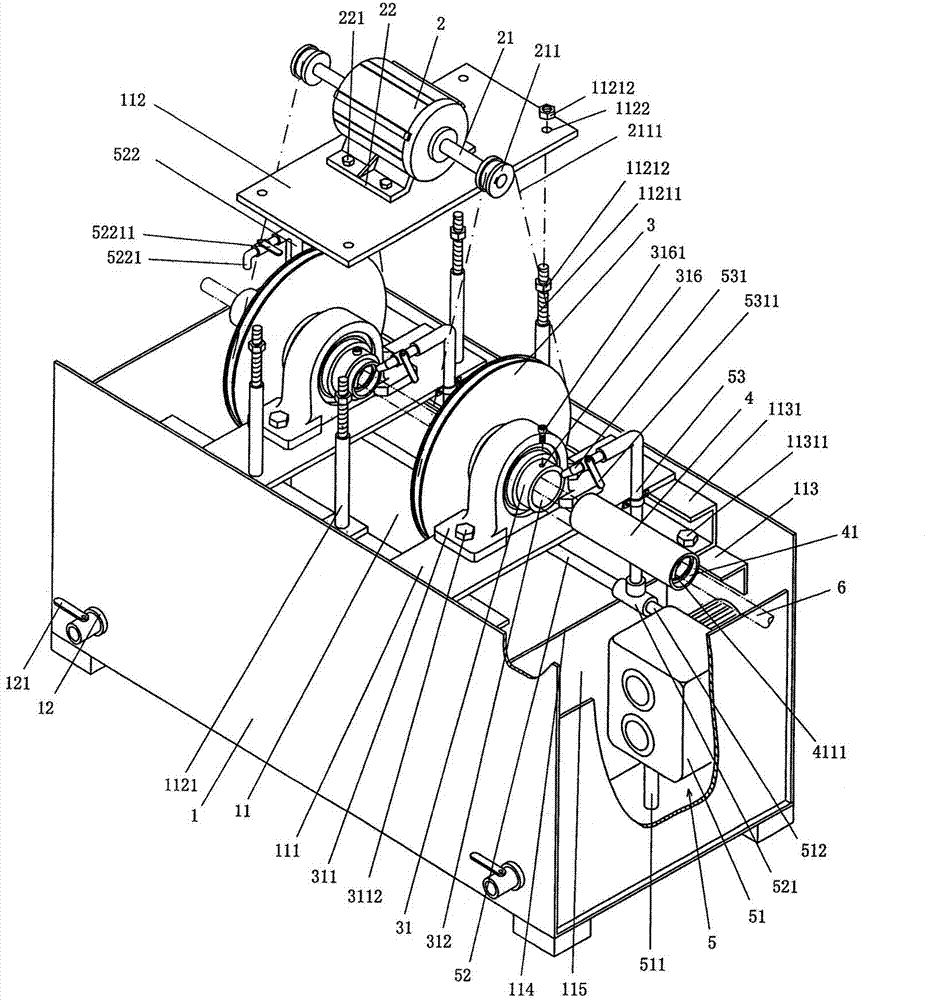
[0025] See figure 1 , a cleaning liquid tank body 1 with a rectangular parallelepiped structure is provided, the upper part of the cleaning liquid tank cavity 11 of the cleaning liquid tank body 1 is open, that is, not closed, and is set in the cleaning liquid tank cavity 11 There is a tank cavity partition plate 114, and the right end of the cleaning liquid tank tank cavity 11 is formed by the tank cavity separating plate, that is, a cleaning liquid circulation chamber 115 is formed, which is located at the left end of the cleaning liquid tank tank cavity 11. A pair of bearing seat fixing plates 111 and a motor support plate 112 are fixed on the upper part. The pair of bearing seat fixing plates 111 are parallel to each other, and one motor support plate 112 corresponds to the upper part between the pair of bearing seat fixing plates 111 in an empty state. .

[0026]Preferably, a sewage discharge interface 12 is provided on the tank wall of one side in the length direction o...

Embodiment 2

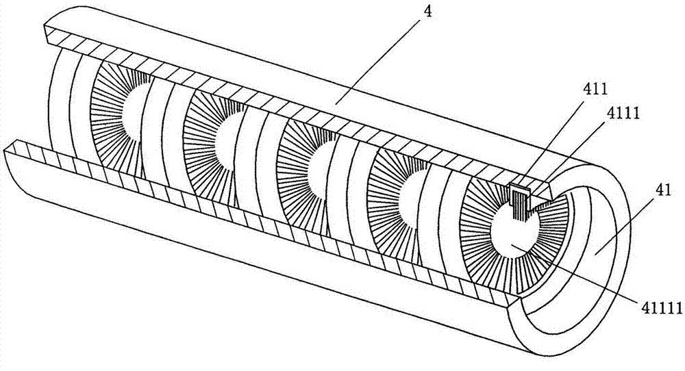
[0040] See Figure 4 , on the inner wall of the brush lumen 41 of the brush tube 4, a straight brush positioning groove 411 is opened in an interval state, and the hair brush 4111 is a straight brush, which is inserted into the straight brush positioning groove Inside 411. Preferably, the cross-sectional shape of the straight brush positioning groove 411 is designed as a dovetail shape, and the steel pipe 6 is cleaned by a group of radially distributed brushes 4111 . All the other are the same as the description to embodiment 1.


PUM


Abstract

The invention provides a steel pipe cleaning device, and belongs to the field of metal pipe cleaning machines. The steel pipe cleaning device comprises a cleaning fluid box body and a circulating fluid supply mechanism. A cleaning fluid recycling cavity is formed in the right end of a cavity of the box body, bearing block fixing plates and a motor supporting plate are fixed to the left end of the cavity, shaft sleeve driving wheels are arranged on the bearing block fixing plates, a motor is arranged on the motor supporting plate, motor shaft driving wheels are fixed to the two ends of a motor shaft, one end of a driving belt is arranged on the motor shaft driving wheels, the shaft sleeve driving wheels are sleeved with the other end of the driving belt, one end of each shaft sleeve is fixed to the center of the corresponding shaft sleeve driving wheel, the other end of each shaft sleeve is supported by a corresponding shaft sleeve bearing block, the shaft sleeve bearing blocks are fixed to the bearing block fixing plates, a brush pipe is fixed into shaft sleeve cavities, brush positioning grooves are formed in the inner wall of a brush pipe cavity and in the length direction, and brushes are embedded into the positioning grooves. The circulating fluid supply mechanism is arranged in the cleaning fluid recycling cavity. The structure is simplified, and the brushes make good contact with the outer wall of a steel pipe; transition links are fewer; the brushes have the permanent cleaning effect on the steel pipe, and the cleaning quality is good.

Description

technical field [0001] The invention belongs to the technical field of metal pipe cleaning machinery, and in particular relates to a steel pipe cleaning device. Background technique [0002] During the process of rolling steel pipes in the pipe rolling mill, the wall of the steel pipe, especially the outer wall, is polluted by cold rolling oil, but when the steel pipe enters the commercial channel, it must be kept clean. Therefore, steel pipe manufacturers usually clean the steel pipe before leaving the factory. Pickling. Specifically: the steel pipe is introduced into the pickling tank, and the oil stain attached to the steel pipe is removed by nitric acid, hydrofluoric acid or other similar acid solutions with a concentration (mass percentage concentration) of about 30-45%. Although this method can guarantee the cleaning effect of the steel pipe surface, it has the following disadvantages: the one, the acid liquid can damage the workers' limbs when cleaning, and there are...

Claims


Application Information

Patent Timeline
Patent Type & Authority Applications(China)
IPC IPC(8): B08B9/023B21B45/02
CPCB08B9/023B21B45/0275Y02P70/10
Inventor 高育军徐剑
Owner CHANGSHU WATER SUPPLY & SEWERAGE WORKS CO LTD
Why Eureka
Try Eureka