Reflow process welding method

A soldering method and reflow soldering technology, applied in soldering equipment, manufacturing tools, metal processing, etc., can solve problems such as bottom plate pollution, flux overflow, etc., and achieve the effect of solving pollution problems

Active Publication Date: 2014-07-16
WUXI CHINA RESOURCE MICRO ASSEMBLY TECH
View PDF5 Cites 24 Cited by
  • Summary
  • Abstract
  • Description
  • Claims
  • Application Information

AI Technical Summary

Benefits of technology

This new technology uses both reflux-soluble solvents (referred to also called “reflow agents”) and heat to improve solder quality at low temperatures without causing harm or environmental concerns associated therewith. By removing these materials beforehand after printing it onto the component being joined by this technique, no residue remains that could affect its properties when exposed later under different conditions such as humidity or pressure.

Problems solved by technology

This technical issue addressed during electronic assembly includes finding ways to improve the efficiency and effectiveness of reflux solder techniques while reducing environmental impact associated therewith. Specifically, the current method involves manual application of soluble resin onto the surfaces being joined together before cooling them down quickly. However, these methods have drawbacks like low throughput rates when applied over long distances without sagging out any unwanted residue. Additionally, they require excessive amounts of fluxes to flow properly, leading to waste and potential defect issues. Therefore, new solutions aim towards improving the performance and durability of refrigeration solderings are needed.

Method used


Image

  • Reflow process welding method
  • Reflow process welding method
  • Reflow process welding method

Examples


Embodiment 1

[0027] Direct bonded copper substrate is an electronic basic material made by directly sintering copper foil on the ceramic surface using DBC (Direct Bonded Copper) technology. Because the copper-clad ceramic substrate has excellent thermal cycle performance, stable shape, good rigidity, high thermal conductivity, and high reliability, the copper-clad surface can be etched with various graphics characteristics, and it is a pollution-free and pollution-free It is a green product with a wide range of operating temperatures, from -55°C to 850°C, and its thermal expansion coefficient is close to that of silicon. Its application fields are very wide: it can be used in semiconductor refrigerators, electronic heaters, high-power power semiconductor modules, and power control circuits. , Power hybrid circuits, intelligent power components, high-frequency switching power supplies, solid state relays, automotive electronics, aerospace and military electronic components, solar panel compo...

Embodiment 2

[0036] The difference between this embodiment and embodiment 1 is that in step 4, the coating area of ​​the flux is 90% of the area of ​​the alloy welding layer.

Embodiment 3

[0038] The difference between this embodiment and the preceding embodiments is that the flux used in step 4 is liquid flux. Compared with solid flux, liquid flux has high surface coating efficiency, easy operation, and good uniformity. The proportion is light. During the reflow soldering process, the liquid flux will appear in gaseous form, so there will be no flux residue, and the effect is better. The liquid flux used in this embodiment is the flux of NCX-FS manufactured by ALPHA Company.

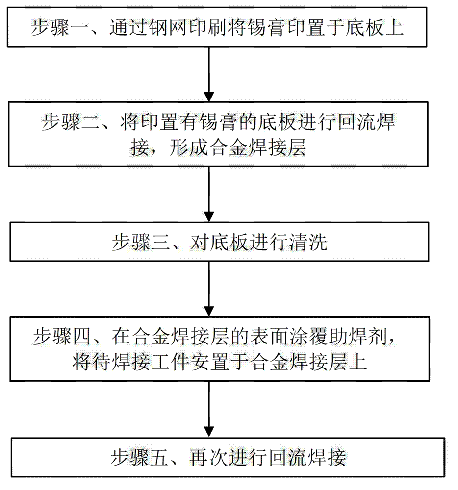
[0039]It can be seen from the above technical scheme that the method of the present invention uses two reflow soldering methods to solder the components. When performing the first reflow soldering in step 2, the reflow soldering temperature is set at the reference temperature N°C (that is, the solder paste used Since the reflow soldering temperature is not set high, the flux in the solder paste has not been subjected to high temperature when cleaning after the reflow soldering, and the o...


PUM


Abstract

A reflow process welding method includes the steps: firstly, printing solder paste on a bottom plate through metal stencil printing; secondly, performing reflow welding for the bottom plate printed with the solder paste, forming an alloy welding layer on the bottom plate, and attaching soldering flux separated out from the solder paste on the surface of the bottom plate; thirdly, cleaning the bottom plate and removing the soldering flux separated out from the solder paste on the surface of the bottom plate; fourthly, coating the surface of the alloy welding layer with the soldering flux, and placing a workpiece to be welded on the alloy welding layer coated with the soldering flux; fifthly, performing reflow welding again. The size of the solder paste is same as that of the workpiece to be welded. The melting-point temperature of the solder paste is reference temperature N DEG C. Compared with the prior art, the process method is more convenient to operate and lower in cost, pollution caused by the soldering flux in the reflow process is avoided, and the method is particularly applicable to surface welding with a large-area contact surface.

Description


Claims


Application Information

Patent Timeline
Owner WUXI CHINA RESOURCE MICRO ASSEMBLY TECH
Why Eureka
Try Eureka