Novel linear rolling and sliding composite guide rail pair

A guide rail pair and straight line technology, applied in the field of guide rail pairs, can solve problems such as difficulty in meeting performance indicators and precision requirements of heavy-duty machine tools, large contact area of ​​sliding guide rails, poor vibration resistance, poor rigidity, etc., and achieve excellent manufacturing process and good motion performance , the effect of large carrying capacity

Inactive Publication Date: 2014-07-16
NANJING UNIV OF SCI & TECH
View PDF8 Cites 9 Cited by
  • Summary
  • Abstract
  • Description
  • Claims
  • Application Information

AI Technical Summary

Problems solved by technology

[0006] The rolling guide rail is made of rolling elements placed between the guide part and the moving part, and can make the matching two guide rail surfaces not directly contact, so it has small frictional resistance, good follow-up and high-speed motion performance, positioning accuracy and repeatability It has the advantages of high positioning accuracy, but its contact stress is large under heavy load, and its vibration resistance and rigidity are poor.
[0007] The sliding guide rail has a large contact area, and most of them use inlaid guide rails or plastic-coated guide rails, which have large bearing capacity, good vibration resistance and rigidity, but their dynamic and static friction is relatively large, and their motion sensitivity is low. They are easy to "crawl" and wear at low speeds. , the disadvantage of short service life
[0008] The hydrostatic guideway adopts liquid friction, and the oil film has good vibration resistance, but its structure is complicated, the cost is high, and maintenance is difficult, so it has not been widely used.
[0009] The above types of guide rails have their own advantages and disadvantages. If rolling guide rails or sliding guide rails are used alone, it is difficult to meet the ideal performance indicators and accuracy requirements of heavy-duty machine tools.

Method used


Image

  • Novel linear rolling and sliding composite guide rail pair
  • Novel linear rolling and sliding composite guide rail pair
  • Novel linear rolling and sliding composite guide rail pair

Examples


Embodiment 1

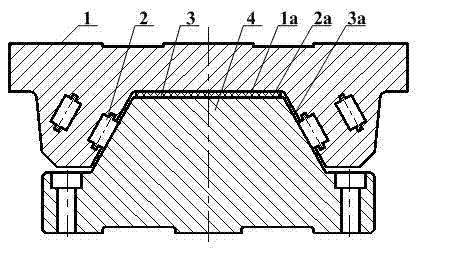
[0028] A new type of linear rolling-sliding composite guide rail pair of the present invention comprises a guide rail 4 and a slider 1 that cooperate with each other, the guide rail 4 is a trapezoidal guide rail, the two sides of the trapezoidal guide rail are guide surfaces 3a, and the upper surface of the trapezoidal guide rail is bearing surface 2a,

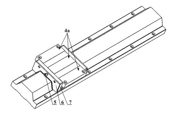
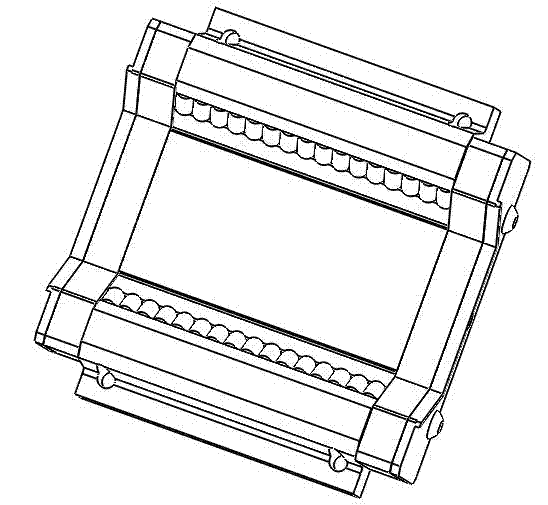
[0029] A trapezoidal groove matching the trapezoidal guide rail is provided at the bottom of the slider 4, and a row of cylindrical roller rows 2 are respectively arranged on the two sides of the trapezoidal groove along the length direction, and the upper surface 1a of the trapezoidal groove of the slider 4 and the load bearing The flexible belt 3 of the guide rail is arranged along the length direction of the guide rail 4 between the surfaces 2a.

[0030] The material of the guide rail 4, the cylindrical roller and the slide block 1 is steel. Both the guide surface 3a and the bearing surface 2a of the guide rail are quenche...

Embodiment 2

[0033] A new type of linear rolling-sliding composite guide rail pair of the present invention comprises a guide rail 4 and a slider 1 that cooperate with each other, the guide rail 4 is a trapezoidal guide rail, the two sides of the trapezoidal guide rail are guide surfaces 3a, and the upper surface of the trapezoidal guide rail is Bearing surface 2a.

[0034] The bottom of the slider 4 is provided with a trapezoidal groove matching the trapezoidal guide rail. Two rows of cylindrical roller columns 2 are respectively arranged on the two sides of the trapezoidal groove along the length direction. The upper surface 1a of the trapezoidal groove of the slider 4 and the load bearing The flexible belt 3 of the guide rail is arranged along the length direction of the guide rail 4 between the surfaces 2a.

[0035] The material of the guide rail 4, the cylindrical roller and the slide block 1 is steel. Both the guide surface 3a and the bearing surface 2a of the guide rail are quenche...


PUM


Abstract

The invention discloses a novel linear rolling and sliding composite guide rail pair, comprising a guide rail and a sliding block fit with each other, wherein the guide rail is trapeziform, two side faces of the trapeziform guide rail are guiding faces, the upper surface of the trapeziform guide rail is a bearing surface, the bottom of the sliding block is provided with a trapeziform groove fit with the trapeziform guide rail, the two side faces of the trapeziform groove are respectively provided with at least one row of cylindrical rollers along the length direction, a guide rail soft strip is arranged between the upper surface of the trapeziform groove of the sliding block and the bearing surface of the trapeziform guide rail along the length direction of the guide rail. The novel linear rolling and sliding composite guide rail pair integrates the advantages of a rolling guide rail and a sliding guide rail, ensures the guiding and positioning accuracies of the motion guide rail and the bearing capacity of the guide rail and simultaneously reduces motion resistance reasonably in the case of loading heavily and cutting heavily, promotes sensitivity, rigidity and vibration resistance of the motion guide rail, improves machining efficiency and prolongs the service life of the guide rail.

Description

technical field [0001] The invention relates to the technical field of guide rail pairs, in particular to a novel linear rolling-sliding composite guide rail pair. Background technique [0002] With the rapid development of China's economy, large-scale projects such as high-speed railways, wind power equipment, domestic large aircraft projects, aerospace equipment, automobile manufacturing equipment and engineering machinery manufacturing have performance requirements for heavy-duty CNC machine tools that can achieve heavy-duty, high-speed and high-torque cutting increasing day by day. [0003] Guide rail is one of the core components of heavy-duty CNC machine tools, which largely determines the rigidity, accuracy and precision retention of heavy-duty CNC machine tools. [0004] The executive components (spindle box, tool holder, workbench) of heavy-duty CNC machine tools are heavy, which puts forward higher requirements for the bearing capacity of the guide rail and the mo...

Claims


Application Information

Patent Timeline
IPC IPC(8): B23Q1/01
CPCB23Q1/017
Inventor 袁军堂汪振华杨尧
Owner NANJING UNIV OF SCI & TECH
Why Eureka
Try Eureka