
Brushing device for metal bar

A metal rod and bristle technology, which is applied in the directions of grinding drive devices, metal processing equipment, grinding machine parts, etc., can solve the problems of wear and tear of the brush wheel, easy damage, deformation of the rod to be processed, etc., and achieves simple structure and convenient adjustment. , the effect of prolonging the service life

Inactive Publication Date: 2014-07-16
江苏薪泽奇机械股份有限公司
View PDF8 Cites 10 Cited by
  • Summary
  • Abstract
  • Description
  • Claims
  • Application Information

AI Technical Summary

Problems solved by technology

In the traditional metal rod bristle device, the bristle shaft (that is, the planetary gear shaft) is subjected to the rotational load on the side of the bristle wheel, so that the bristle shaft in the cantilever transmission state is subjected to a large radial load at the planetary gear and is easily damaged. Planetary gears and transition gears are vulnerable to damage
In addition, in the traditional metal rod brushing device, since the central shaft and the revolving seat rotate together, the rod to be processed passing through the central shaft can only be supported by the feeding end, which will easily cause the lower brush wheel to wear more seriously than the upper brush wheel. After a long time, the rod to be processed will be deformed during the processing, which will affect the product quality

Method used


Image

  • Brushing device for metal bar
  • Brushing device for metal bar
  • Brushing device for metal bar

Examples


Embodiment Construction

[0020] Specific embodiments of the present invention will be described in detail below in conjunction with the accompanying drawings.

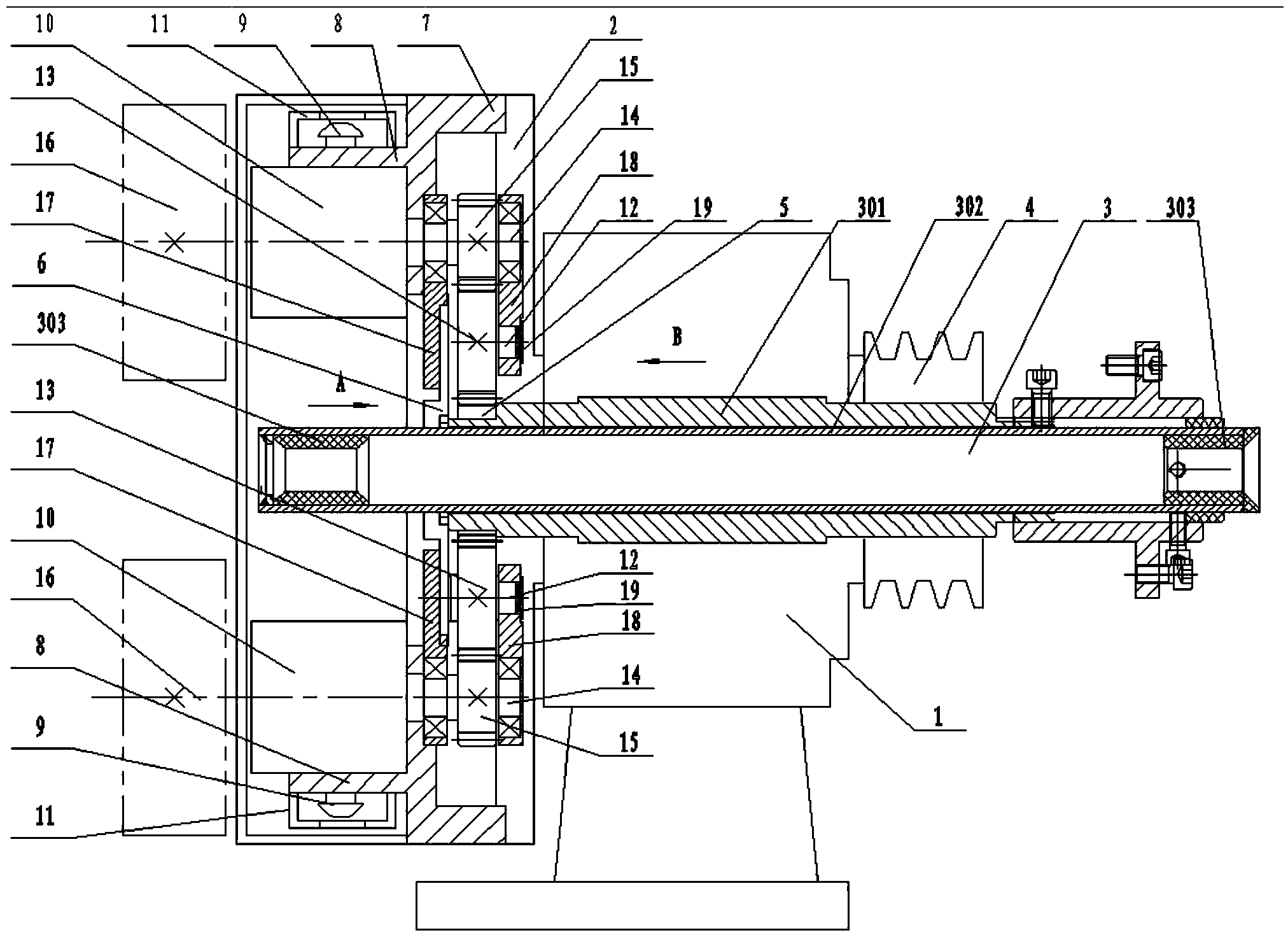
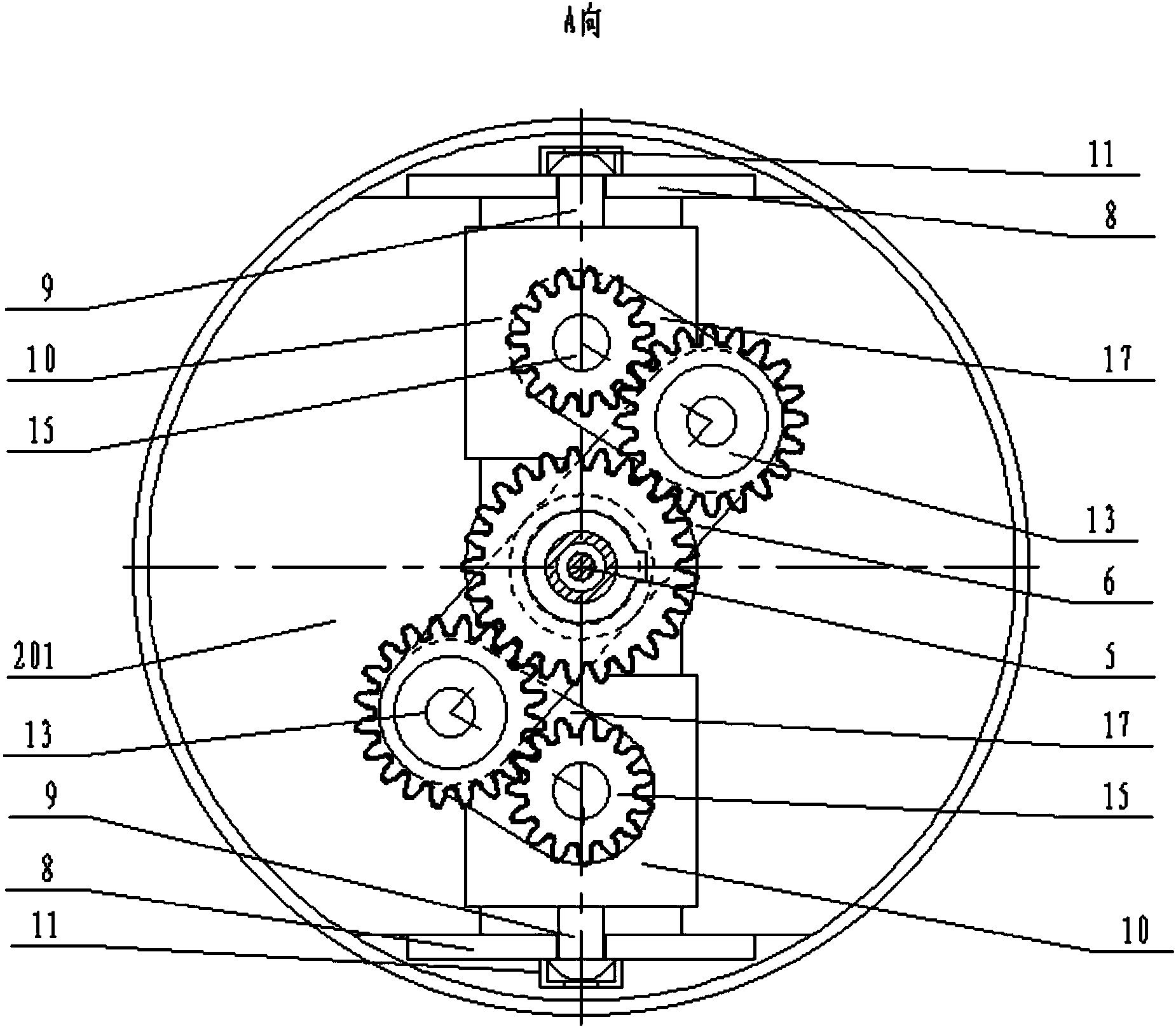
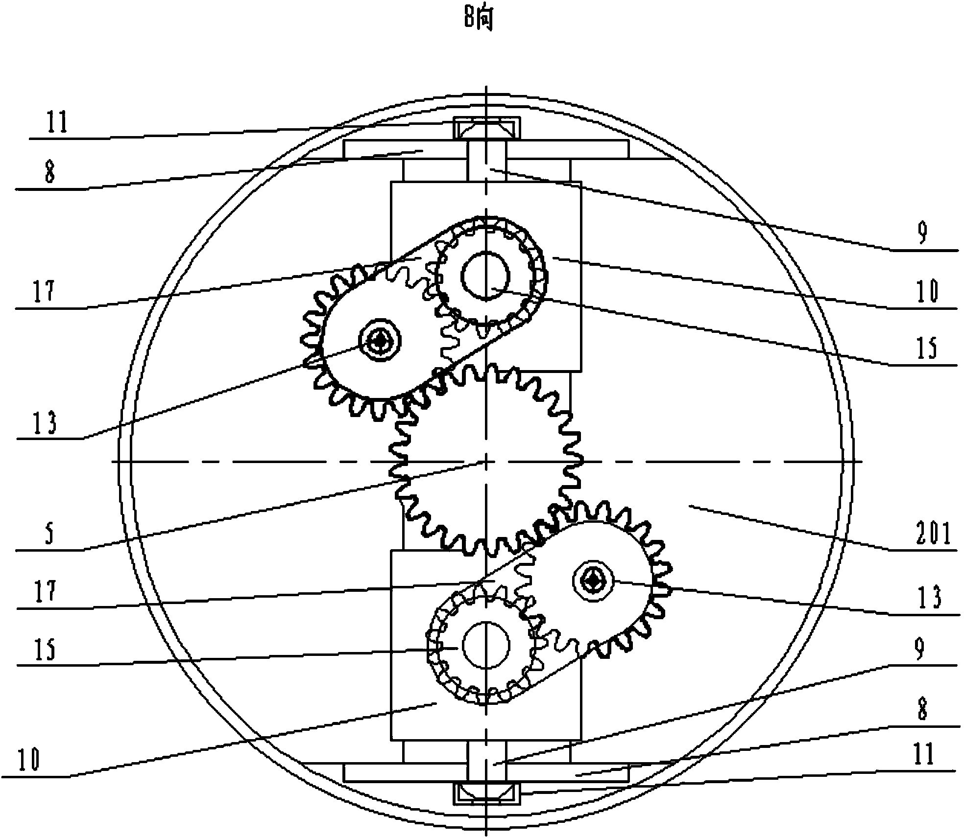
[0021] like Figure 1-3 As shown, a metal rod brushing device includes a base 1, a metal rod brushing device includes a base 1, a hollow shaft 301 is pierced in the base 1, and the central shaft assembly 3 includes a hollow shaft 301 , The hollow shaft 301 is provided with a sleeve 302, and the two ends of the sleeve 302 are respectively detachably provided with a nylon sleeve 303 in the middle for the rod to be processed to pass through. A revolving seat 2 is movably sleeved between the base 1 and the central shaft assembly 3, and a pulley 4 is provided on one side of the revolving seat 2 to drive it to rotate. The hollow shaft 301 passes through the through hole in the middle of the pulley 4. The hollow shaft 301 on the other side of the revolving base 2 are set with a central gear 5, a main connecting rod 6 and a revolving head 7 in sequen...


PUM


Abstract

The invention discloses a brushing device for a metal bar. The brushing device for the metal bar is small in radial load of planet gear and long in service life. The brushing device for the metal bar comprises a machine base, a revolution seat, a hollow shaft and a belt wheel. A sun gear, a main connecting rod and a revolution head are arranged on the hollow shaft above the revolution seat in a sleeved mode in sequence, the revolution head is fixedly connected to the revolution seat, the revolution head is provided with two sliding seats which slide relatively in the radial direction of the revolution head, transition gears meshed with the sun gear through transition gear shafts are arranged on the main connecting rod and on the two sides of the sun gear, planet gear shafts are arranged in the sliding seats in a penetrating mode, one end of each planet gear shaft is provided with a planet gear meshed with the corresponding transition gear in a sleeved mode, the other ends, penetrating through the sliding seats, of the planet gear shafts are provided with brushing wheels, the position, close to the main connecting rod, between the transition gear shafts and the planet gear shafts is provided with an auxiliary connecting rod in a movable sleeved mode, the ends, close to the revolution seat, of the transition gear shafts are provided with connecting plates in a rotating sleeved mode, and the other ends of the connecting plates are arranged at the corresponding positions of the planet gear shafts in a sleeved mode.

Description

technical field [0001] The invention relates to a brushing device for metal rods in the production process of copper-clad aluminum, copper-clad steel and other bimetallic composite wires. Background technique [0002] In the process of aluminum, steel and other metal core rods and wire rods being continuously covered and welded by thin metal strips in the longitudinal direction, in order to realize the rapid metallurgical bonding of the inner surface of the outer metal strip and the outer surface of the inner cladding metal core rod, it is necessary Brush off the oxide film on the outer surface of the metal core rod to expose a fresh metal surface, and roughen the outer surface, so as to ensure the firm bonding quality of the bimetallic composite wire. In the traditional metal rod bristle device, the bristle shaft (that is, the planetary gear shaft) is subjected to the rotating load on the side of the bristle wheel, so that the bristle shaft in the cantilever transmission st...

Claims


Application Information

Patent Timeline
IPC IPC(8): B24B27/033
CPCB24B27/033B24B41/067B24B47/12
Inventor 陆建华
Owner 江苏薪泽奇机械股份有限公司
Learn More