Driving device for underwater hydraulic mechanical arm joints

A manipulator, underwater water technology, applied in the direction of manipulators, manufacturing tools, joints, etc., can solve problems that do not involve joint operation information feedback, unsatisfactory leakage of materials, large volume and weight, etc., to achieve compact structure, light weight, and volume small effect

Inactive Publication Date: 2014-07-16
HARBIN ENG UNIV
View PDF8 Cites 7 Cited by
  • Summary
  • Abstract
  • Description
  • Claims
  • Application Information

AI Technical Summary

Problems solved by technology

[0003] At present, the joint drive technology suitable for underwater manipulators is relatively mature, such as Chinese patent application number 200810063943.3, named "Upper Arm of Underwater Manipulator" and Chinese Patent Application No. 200810063942.9, named "Underwater Manipulator Shoulder Joint" Among them, the driving device of the manipulator is a linear hydraulic cylinder, and the driving device of the manipulator joint composed of the linear hydraulic cylinder limits the angle range that the joint can rotate; In the patent document of , the structural form of the manipulator driving device is a helical swing cylinder, which has a relatively complex structure, large volume and weight, and does not involve the feedback of joint operation information.
[0004] Due to the large difference between the viscosity of fresh water or sea water and the common hydraulic oil, the above-mentioned commonly used hydraulic joint drive devices have large internal leakage, external leakage and materials that cannot meet the requirements of use; at the same time, in order to improve the control accuracy of the manipulator , the manipulator joint drive device needs to be designed with closed-loop feedback adjustment

Method used


Image

  • Driving device for underwater hydraulic mechanical arm joints
  • Driving device for underwater hydraulic mechanical arm joints
  • Driving device for underwater hydraulic mechanical arm joints

Examples


Embodiment Construction

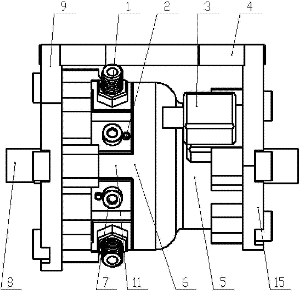
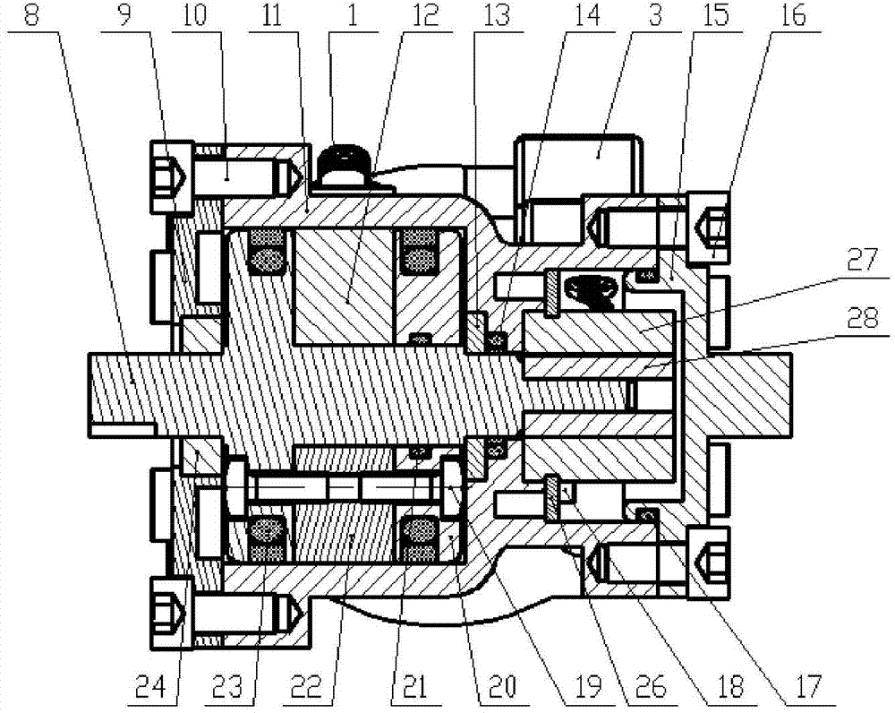
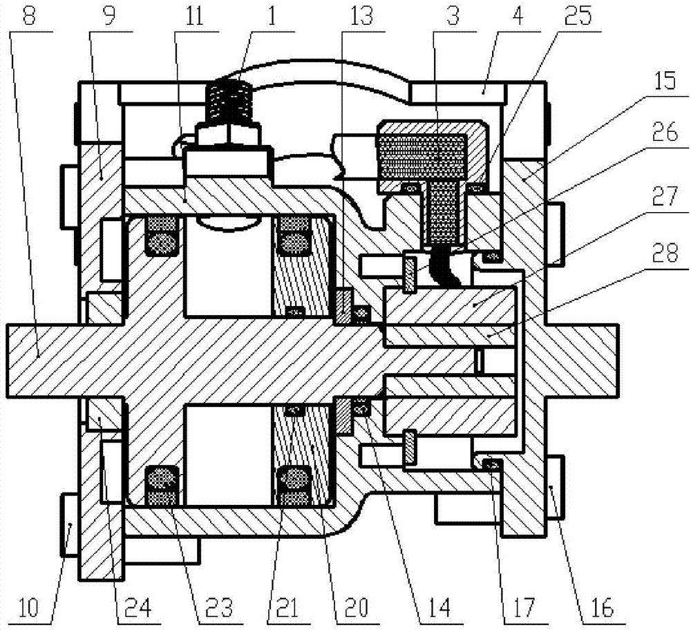
[0027] The present invention is described in more detail below in conjunction with accompanying drawing example:

[0028] combine Figure 1~1 1. The purpose of the patent of this invention is to provide an underwater hydraulic manipulator joint drive device that uses seawater or fresh water as the hydraulic medium, which is light in weight, small in size, easy to install, large in driving force and pollution-free. As the most important part of the underwater hydraulic manipulator, the device provides the driving force for the manipulator to work underwater, and feeds back parameters such as the angle and angular acceleration of the manipulator through the position detection part to facilitate the control of the joints of the manipulator by the upper computer; the device The water hydraulic drive can provide a large and stable driving torque for the manipulator, and the water hydraulic method is more environmentally friendly than the oil hydraulic (the hydraulic medium leaks to...


PUM


Abstract

The invention aims to provide a driving device for underwater hydraulic mechanical arm joints. The driving device is composed of a hydraulic driving portion, a position detection portion and a front joint and rear joint connection portion. The position detection portion and the hydraulic driving portion are achieved through connection of a driving rotor output shaft. The hydraulic driving portion is composed of a driving rotor assembly and a driving stator and located through supporting of a left rolling bearing and a right sliding bearing, and a sealing O-shaped ring and a sealing Glyd ring are adopted for preventing leakage. The driving rotor assembly is composed of a driving rotation shaft, a driving rotor, a rotor sealing Glyd ring, a rotor O-shaped sealing ring and a driving rotor right end cover. The rotor is installed on the driving rotation shaft in a fastening mode. The surface, making contact with the end cover, of the rotor is painted with sealant. The inner hole of the right end cover is painted with sealant and installed on one side of the rotor, the rotation shaft, the rotor and the rotor right end cover are locked through rotor pre-tightening screws, and therefore the whole assembly is formed. The driving device is suitable for driving the joints of an underwater operation mechanical arm.

Description

technical field [0001] The invention relates to a driving device, in particular to an underwater driving device. Background technique [0002] The ocean is rich in biological resources and mineral resources. The development and utilization of the ocean by human beings is inseparable from underwater operation equipment. Underwater manipulator is an operation tool that is often equipped with underwater operation equipment, and underwater hydraulic manipulator, as an important branch of it, has become a research hotspot. The underwater hydraulic manipulator has the advantages of large driving torque and good stability. The hydraulic system has a better weight-to-power ratio, which is conducive to reducing the overall weight and volume of the manipulator; With the increasing requirements for environmental protection, safety and energy saving of hydraulic manipulators, water hydraulic technology based on fresh water or sea water as the driving medium has attracted more and more ...

Claims


Application Information

Patent Timeline
Patent Type & Authority Applications(China)
IPC IPC(8): B25J17/00B25J19/00
Inventor 张铭钧杨超姚峰王玉甲赵文德马小委赵克楠
Owner HARBIN ENG UNIV
Why Eureka
Try Eureka