
Duct wing system and aircraft using same

An aircraft and wing technology, applied in the field of ducting, can solve the problems such as the limited ability of ducted wing and supporting wing to increase the power and the weak tip vortex, so as to eliminate vibration, eliminate swirl torsion, and have a good vision. Effect

Inactive Publication Date: 2014-07-16
龙川
View PDF6 Cites 13 Cited by
  • Summary
  • Abstract
  • Description
  • Claims
  • Application Information

AI Technical Summary

Problems solved by technology

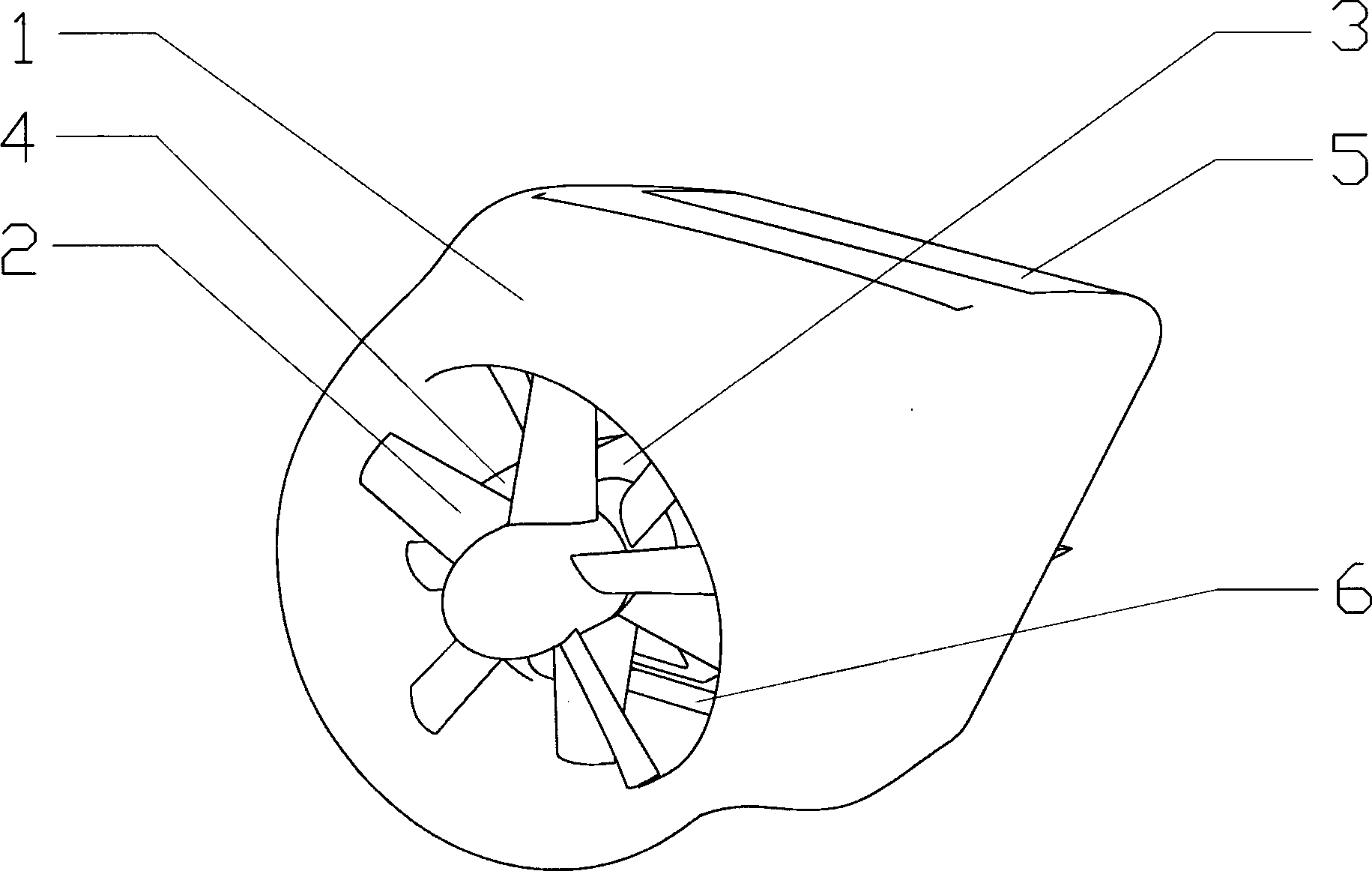
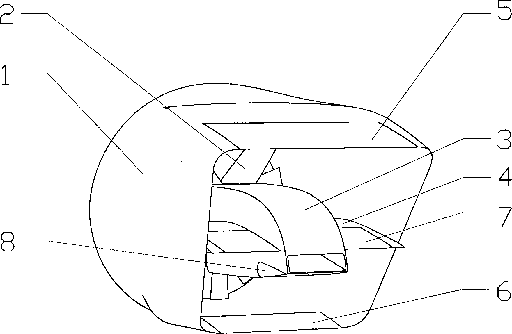
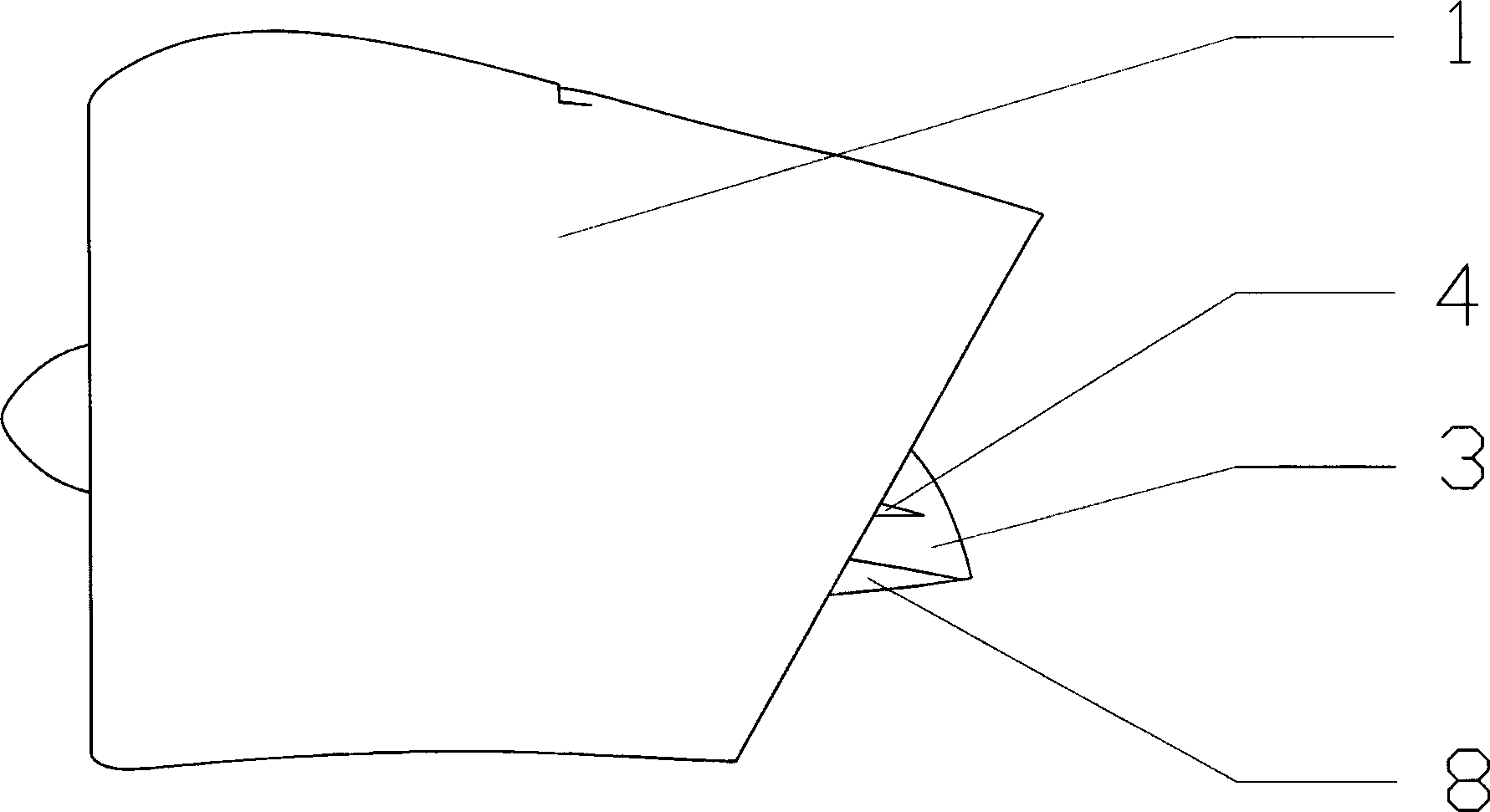
[0002] Chinese invention patent ZL201110086570.3 discloses a ducted wing system and an aircraft using the ducted wing system. The ducted wing system described in the patent includes a ducted wing and a For the fan at the position, the leading edge of the ducted wing is ring-shaped, and the trailing edge is a trapezoid with a wide top and a narrow bottom. The leading edge of the ducted wing, the trailing edge, and the connecting section between the two are taken as a whole. The longitudinal section has an airfoil. The trailing edge of the ducted wing gradually slopes backward from the bottom to the top. The trailing edge of each layer is equipped with trailing edge flaps; the engine driving the fan is installed in the inner space of the ducted wing through a support wing, and the trailing edge of the supporting wing is provided with a trailing edge flap; when the fan rotates, it can accelerate the air flow under the ducted wing at the same time. The airflow on the surface of the half inner wall and the surface airflow on the inner and outer walls of the upper half of the ducted wing, and the airflow on the upper and lower surfaces of the accelerated support wing, but the fan of the ducted wing system is a single set, which has slip flow torsion when rotating. Wings and supporting wings have limited power lift capability; since the leading edge of the ducted wing gradually slopes backward from the bottom to the top, the fan blades are located in the lower front half of the ducted wing when they rotate to the lower half of the ducted wing The inner space of the fan blade, the tip of the fan blade is close to the inner wall of the leading edge of the lower half of the ducted wing with a gap as a gap. The vortex at the tip is very weak. In the outer space of the upper part of the front part of the wing, the blade tip vortex is very strong. In this way, the fan blade tip vortex has periodic changes, which will cause strong vibration of the fan and the vibration of the aircraft, which will affect the comfort and cause structural damage. Fatigue; when the fan rotates, some fan blades are exposed outside the duct, the noise will leak out, and it is unsafe; the aircraft using the ducted wing system will have two ducted wing systems symmetrically arranged in the fuselage. When the ducted wing system takes off and lands vertically and flies horizontally, the fan rotates to face the occupants in the cockpit. When foreign matter is inhaled and the fan blades are damaged and ejected, it may cause injury to the occupants; There is a built-in ducted fan that produces lift fan function. Since the built-in ducted fan of the nose is relatively close to the driver and passengers in the front row in the cockpit, when foreign matter is inhaled, the blades of the built-in ducted fan will be damaged. When it is shot out, it may also cause damage to the passengers in the front row of the cockpit; the aircraft with the canard layout needs to maintain a head-up attitude when it takes off and lands vertically, but the built-in ducted fan is set at the nose, and the fan The larger the diameter, the corresponding longer the nose, resulting in poor vision for the pilot when the aircraft is taking off and landing vertically; the larger the fan diameter, the heavier the weight, and it is heavy when flying horizontally, which is not economical

Method used


Image

  • Duct wing system and aircraft using same
  • Duct wing system and aircraft using same
  • Duct wing system and aircraft using same

Examples


Embodiment 1

[0045] The aircraft that can be formed by the combination of the fuselage and the fuselage and the ducted wing system described in the first embodiment, and the aircraft that can be formed by the combination of the fuselage described in the second embodiment and the fuselage and the ducted wing system The other parts of the aircraft have the same structure, and the aircraft that can be formed by the combination of the fuselage 12 and the fuselage 12 and the ducted wing system in Embodiment 1 is taken as an example to continue to describe the other parts of the aircraft.

[0046] like Figure 9 , 10 , 11, 13, 14, and 15, the lift fan 27 is arranged in the tail cone of the fuselage 12; the air inlet of the lift fan 27 is provided with a cover plate that can be opened and closed toward the fuselage 12 head direction as required 21. The air outlet is provided with vertically arranged louvers 25 that can be opened and closed as required; the lift fan 27 is a coaxial counter-rotati...

Embodiment 2

[0063] The fuselage 29 described in the second embodiment and the combination of the fuselage 29 and the ducted wing system can form an aircraft in the form of a business jet. The working process of the domestic form of aircraft that can be formed by the combination of the wing systems is the same.

[0064] In this embodiment, the control stabilization system needs to be used for artificial stabilization when the aircraft is flying.

[0065] Since two ducted wing systems are arranged on both sides of the front part of the fuselage 29 of the aircraft in this embodiment, and the trapezoidal trailing edge of each ducted wing 1 has two left and right façades, these façades are arranged on the same The vertical tail before the center of gravity of the aircraft makes the aircraft lack of heading stability, so the aircraft needs to use a control stabilization system in conjunction with the vertical stabilizer 19 and the rudder 20 to maintain the heading stability of the aircraft. , ...


PUM


Abstract

The invention discloses a duct wing system comprising a duct wing, and a fan arranged at the front edge part of the duct wing, wherein the front edge part of the duct wing is shaped like a ring; the rear edge part of the duct wing is shaped like a trapezoid which is wide in upper part and narrow in lower part; the ring of the front edge part of the duct wing is in smooth connection with the trapezoid which is wide in upper part and narrow in lower part with and arranged at the rear edge part; the fan is a coaxial counter rotating fan and free of race rotation; the inner wall of the ring-shaped front edge part of the duct wing completely wraps the fan to reduce a tip vortex of the fan; meanwhile, the noise is shielded; the duct wing system is relatively safe. A gap communicated with the inner wall surface and the outer wall surface of the duct wing is formed in the upper part of the duct wing; the fan slip flow can enable power of the duct wing to be increased according to the groove wing effect and the gap wing effect. An aircraft using the duct wing system, disclosed by the invention, can vertically take off and land and horizontally fly, the vertical taking off and landing states and the horizontal flight state are stably converted, the duct wing system is good in safety, and good in economical efficiency, and the sight of a pilot is good.

Description

technical field [0001] The invention relates to a duct, in particular to a ducted wing system and an aircraft using the system. Background technique [0002] Chinese invention patent ZL201110086570.3 discloses a ducted wing system and an aircraft using the ducted wing system. The ducted wing system described in the patent includes a ducted wing and a For the fan at the position, the leading edge of the ducted wing is ring-shaped, and the trailing edge is a trapezoid with a wide top and a narrow bottom. The leading edge of the ducted wing, the trailing edge, and the connecting section between the two are taken as a whole. The longitudinal section has an airfoil. The trailing edge of the ducted wing gradually slopes backward from the bottom to the top. The trailing edge of each layer is equipped with trailing edge flaps; the engine driving the fan is installed in the inner space of the ducted wing through a support wing, and the trailing edge of the supporting wing is provide...

Claims


Application Information

Patent Timeline
IPC IPC(8): B64C3/58B64C9/02
Inventor 龙川
Owner 龙川
Learn More