Energy-saving system of cooling air hose of glass annealing kiln and cooling method of glass tape

A cooling air duct and energy-saving system technology, applied in the field of annealing kiln, can solve the problems of affecting the stability of annealing temperature, increasing power consumption, low control precision and regulating valves, so as to improve energy utilization rate, reduce the difficulty of control, and avoid mutual interference Effect

Inactive Publication Date: 2014-07-16
洛阳建材机械厂
View PDF4 Cites 5 Cited by
  • Summary
  • Abstract
  • Description
  • Claims
  • Application Information

AI Technical Summary

Problems solved by technology

At present, in the annealing kiln of the glass production line, the high-temperature glass plate emits a large amount of heat when cooling in the annealing kiln, and the cooling system of the annealing kiln needs to discharge the heat out of the kiln through heat exchange; there are many existing annealing kiln ventilation and cooling systems There are many butterfly valves on the ventilation pipeline. By adjusting the opening of the butterfly valve, the air volume of each air channel is adjusted. The application of the butterfly valve on the pipeline realizes the function of air volume adjustment, and at the same time increases the resistance of the pipeline and increases the consumption of electric energy. Therefore, , how to reduce the resistance on the pipeline and at the same time realize the adjustment of the air volume of each air channel is the key to reduce the energy consumption of the ventilation and cooling system of the annealing kiln
[0003] The cooling air adopts natural wind. Due to the large change in air temperature due to seasons and day and night ambient temperature, the amount of cooling air varies greatly. For example, in winter, only a small amount of air is needed to meet the process requirements; During the process, the lateral temperature distribution is high in the middle and low in the side; in production, the automatic butterfly valves at different positions have different openings. Usually, the annealing kiln fans use motors with rated output power. When it is necessary to reduce the air volume, generally use Adjust the opening of the valv

Method used


Image

  • Energy-saving system of cooling air hose of glass annealing kiln and cooling method of glass tape
  • Energy-saving system of cooling air hose of glass annealing kiln and cooling method of glass tape

Examples


Embodiment 1

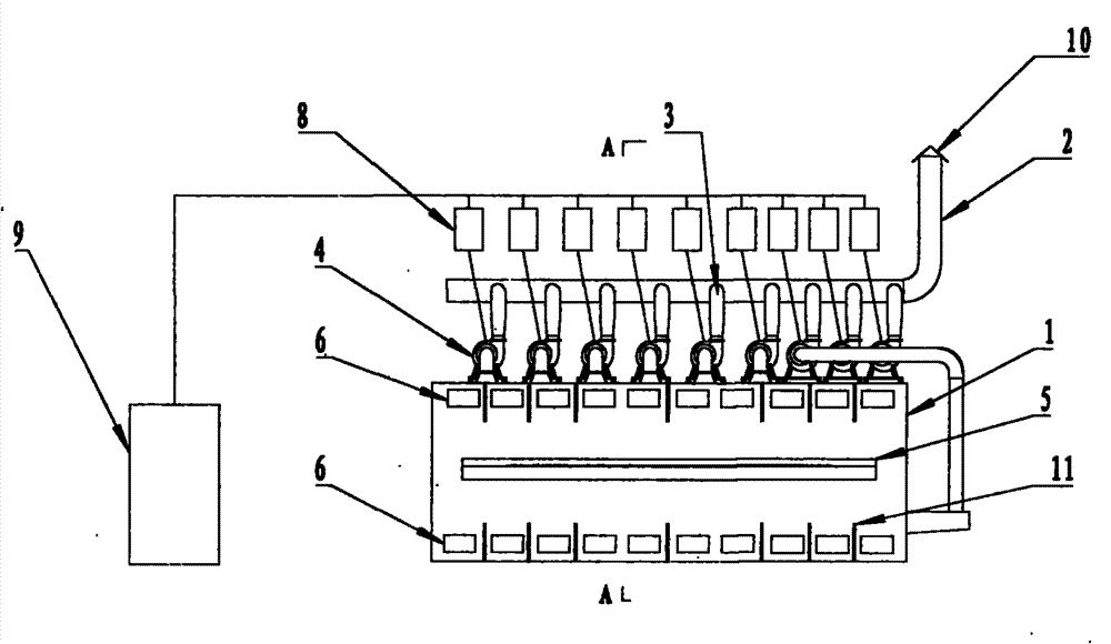
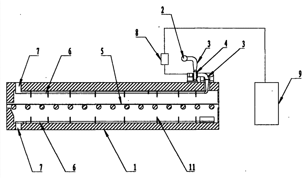
[0021] A main air duct 2 is arranged outside the annealing kiln 1, an air outlet 10 is arranged at one end of the main air duct 2, and at least two branch air ducts 3 outside the kiln are arranged on one side of the main air duct 2; a glass belt 5 is arranged in the middle of the annealing kiln 1, Multiple sets of thermocouples 11 are arranged on the top and bottom of the annealing kiln 1 corresponding to the glass ribbon 5, each group is at least two, and multiple sets of branch air pipes 6 in the kiln are arranged between multiple sets of thermocouples 11 corresponding to the glass ribbon 5, and each group is at least The kiln branch air pipe 6 in the annealing kiln 1 is set corresponding to the kiln external branch air pipe 3 outside the annealing kiln 1, and the upper and lower walls of the annealing kiln 1 are provided with an air inlet 7 corresponding to the kiln internal branch air pipe 6 An industrial computer 9 is set on one side of the annealing kiln 1; a blower fan 4...

Embodiment 2

[0023] The thermocouples 11 above and below the annealing kiln 1 measure the temperature above and below the running glass ribbon 5, and transmit the temperature data to the industrial computer 9, which controls the branch air duct 3 outside the kiln through the frequency converter 8 The speed of the upper fan 4 draws the cold gas from the air inlet 7 of the annealing kiln 1 into the branch air pipe 6 in the kiln, and the cold gas in the kiln branch air pipe 6 exchanges heat with the hot gas in the annealing kiln 1 indirectly, and the heat exchange recedes The cold air in the furnace 1 cools the glass ribbon 5 evenly, and the cold air in the branch air pipe 6 inside the kiln is heated and then enters the branch air pipe 3 outside the kiln and the main air pipe 2, and from the air outlet 10 of the main air pipe 2 Exhaust outside.

Embodiment 3

[0025] After the industrial computer 9 receives the temperature data transmitted by the thermocouple 11, the industrial computer 9 controls the frequency converter 8 according to the set temperature parameters to adjust the speed of the fan 4 on the branch air duct 3 outside the kiln, and increase or decrease the temperature in the kiln in different areas. The air intake of the branch air duct 6 keeps the temperature of the space above or below the glass ribbon 5 at 610°C-380°C, so that the glass ribbon 5 is evenly cooled.


PUM


Abstract

The invention relate to an energy-saving system of a cooling air hose of a glass annealing kiln and a cooling method of a glass tape. Each pipeline is equipped with a draught fan which is provided with a frequency converter, and the frequency converters are freely controlled by an industrial personal computer to reaching the purpose of adjusting the rotating speed of the draught fans, so that each branch air hose is more convenient to control. The size of the cooling air amount of each branch air hose can be conveniently adjusted according to the temperature adjusting demands of glass plates in different regions, so that the temperatures in each region in the annealing kiln is reasonable and the best glass annealing effect is achieved. The equipment investment is reduced, the pipeline system is simplified, the energy utilization rate of the manufacturer is greatly improved and the electric energy consumption of the ventilating system of the annealing kiln is reduced, so that the effect of saving energy and protecting the environment is realized.

Description

technical field [0001] The invention relates to the technical field of annealing kilns of a glass production line, in particular to an energy-saving system for cooling air ducts of a glass annealing kiln and a method for cooling a glass ribbon. Background technique [0002] The annealing kiln is one of the three major thermal equipments in the glass production line. Its function is to reduce the temperature of the glass plate from 600-650°C to 70-90°C in a controlled manner according to the requirements of the annealing process. It adopts all-steel and all-electric structure, which is composed of several sections, and is divided into several zones longitudinally according to the annealing curve. Each zone adopts different heating and cooling systems according to the requirements of glass plate temperature and annealing process, so as to complete good annealing and reasonable cooling. At present, in the annealing kiln of the glass production line, the high-temperature glass p...

Claims


Application Information

Patent Timeline
IPC IPC(8): C03B25/00
Inventor 颜淮祥赵宏勋刘岩王文干甄俊峰赵小涛王慧生张永永李敬伟万红光
Owner 洛阳建材机械厂
Why Eureka
Try Eureka