Star-shaped heat energy power device and working method thereof

A technology for power equipment and thermal energy, applied in mechanical equipment, hot gas variable capacity engine devices, machines/engines, etc., can solve the problems of high manufacturing cost, high cost, complex structure of internal combustion engine radial engine, etc., to achieve maintainability and survival. The effect of good performance, light weight and great potential for power growth

Inactive Publication Date: 2014-07-16
郭远军
View PDF5 Cites 7 Cited by
  • Summary
  • Abstract
  • Description
  • Claims
  • Application Information

AI Technical Summary

Problems solved by technology

[0014] The invention overcomes the problems of high cost of the expansion chamber, compression chamber, heater, cooling chamber, regenerator, etc. in the external combustion engine, and the heat loss is 2-3 times that of the internal combustion engine; it overcomes the need for expansion in the organic Rankine cycle system Engine or steam turbine, the technical problem of high manufacturing cost; overcome the problem of complex structure and high manufacturing cost of internal combustion radial engine

Method used


Image

  • Star-shaped heat energy power device and working method thereof
  • Star-shaped heat energy power device and working method thereof

Examples


Embodiment 1

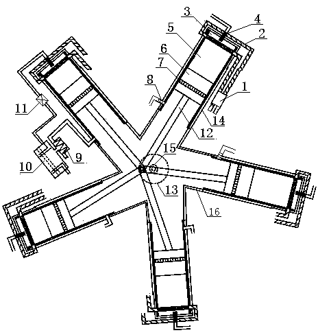
[0027] A star-shaped heat energy power equipment, including heat collector 1, heat preservation pipe 2, gasification reactor 3, atomizer 4, cylinder 5, piston 6, piston ring 7, automatic exhaust valve 8, cooler 9, storage Liquid tank 10, pressure valve 11, connecting rod 12, crankshaft 13, insulating layer 14, rotating shaft 15 and casing 16; On the crankshaft 13, the piston 6 is arranged in the cylinder 5, and the piston ring 7 is arranged on the piston 6; Gasification reactor 3, atomizer 4 is arranged at the inlet end of gasification reactor 3, atomizer 4 is connected to pressure valve 11 through pipeline, and pressure valve 11 is connected to liquid storage tank 10 through pipeline; Gasification reactor 3 is arranged on The top dead center of the cylinder 5; the bottom dead center of the cylinder 5 is provided with an automatic exhaust valve 8, the automatic exhaust valve 8 is connected to the cooler 9 through a pipeline, and the cooler 9 is connected to the liquid storage ...

Embodiment 2

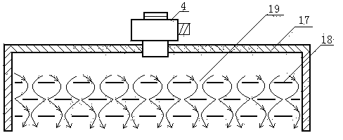
[0029] Like the star-shaped thermal energy power equipment in Example 1, the gasification reactor 3 includes a pressure shell 17, a gasification heat conduction sheet 18, an air hole 19, and an atomizer 4, and the gasification heat conduction sheet 18 is arranged on the pressure shell 17, Air holes 19 are arranged in an array on the gasification heat-conducting sheet 18, and an atomizer 4 is provided at the inlet end of the pressure shell 17; the pressure valve 11 is associated with the crankshaft 13, and the pressure valve is opened and closed five times every time a cycle is completed; The cylinder structure is an example, five cylinders form a star structure, and the five cylinders do work in turn; the number of cylinder groups of a star engine is an odd number, there are 5 cylinders, 7 cylinders, and 9 cylinders. In order to increase power, it can also be multi-row. Stacking, multiple cylinder groups are arranged in several rows, up to 4 rows × 7 cylinders, reaching 28 cyli...


PUM


Abstract

The invention relates to a star-shaped heat energy power device and a working method thereof. The star-shaped heat energy power device comprises heat collectors, heat preservation tubes, gasification reactors, atomizers, air cylinders, pistons, piston rings, automatic exhaust valves, coolers, liquid storage tanks, pressure valves, connection rods, a crank shaft, heat preservation layers, a rotating shaft and a casing; the air cylinders are arranged on the casing and distributed around the crank shaft in a star shape, and the pistons are connected with the crank shaft through the connection rods. The star-shaped heat energy power device of the star-shaped structure is high in rigidity, low in weight, good in reliability, maintainability and survivability, high in power growth potential, and high in rotating speed; the diameters of the air cylinders can be enlarged so as to improve the discharge capacity and power; working media are used circularly, and no pollution is caused; conversion efficiency of heat energy ranges from 65% to 98%; conventional energy consumption can be replaced, economic benefits are high, energy is saved, the environment is protected, and noise is low.

Description

technical field [0001] The invention belongs to the field of thermal power equipment, in particular to a power machine that converts heat energy such as solar energy, geothermal heat, high-temperature gas generated by combustible combustion, internal combustion engine heat or exhaust gas, and high-temperature gas discharged from factories into kinetic energy. Background technique [0002] Traditional power equipment includes steam engine, internal combustion engine and external combustion engine. [0003] Steam engine: Inseparable from the boiler, the whole device is bulky and bulky; the pressure and temperature of the fresh steam cannot be too high, the exhaust pressure cannot be too low, and the thermal efficiency is difficult to improve; it is a reciprocating machine, and the inertia limits the increase of the speed; The working process is discontinuous, and the flow of steam is limited, which limits the improvement of power. [0004] Internal combustion engine: complex ...

Claims


Application Information

Patent Timeline
Patent Type & Authority Applications(China)
IPC IPC(8): F02G1/044
Inventor 郭远军
Owner 郭远军
Why Eureka
Try Eureka