
Flexible structure-variable compressed air energy storage system with vortex machines

A technology of compressed air energy storage and flexible variable structure, which is applied in the direction of compressors, irreversible cycle compressors, pump combinations for elastic fluid rotary piston type/swing piston type, etc., and can solve short-term fast-changing transient power Improve the problems of limited ability, slow dynamic response, and fixed structural power level, etc., to achieve the effect of solving insufficient power stabilization ability, reducing system power loss, and improving dynamic response speed

Active Publication Date: 2014-07-16
QUFU NORMAL UNIV +1
View PDF6 Cites 8 Cited by
  • Summary
  • Abstract
  • Description
  • Claims
  • Application Information

AI Technical Summary

Problems solved by technology

However, the system does not provide effective heat storage control and application methods. At the same time, the two-branch structure has fixed power levels, slow dynamic response, complex structure, and large grid-connected impact current, which can control the long-term slow-varying power fluctuation of new energy, but it is not effective for short-term Limited ability to improve fast transient power
Invention patent ZL201210070884.9 discloses a new type of compressed air energy storage system, which adopts a single-branch energy storage system structure composed of compression and expansion scrolls, and has the following problems: 1) The power level of compression energy storage is fixed, and the power adjustment capability Poor, 2) The scroll machine often works in the state of over / under compression and expansion due to the air pressure of the gas tank, which seriously affects the energy storage efficiency; 3) Compression and expansion heat production and refrigeration seriously affect the aerodynamic conversion efficiency

Method used


Image

  • Flexible structure-variable compressed air energy storage system with vortex machines
  • Flexible structure-variable compressed air energy storage system with vortex machines
  • Flexible structure-variable compressed air energy storage system with vortex machines

Examples


Embodiment Construction

[0019] The present invention will be further described below in conjunction with the accompanying drawings and embodiments.

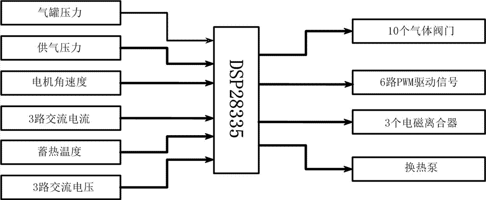
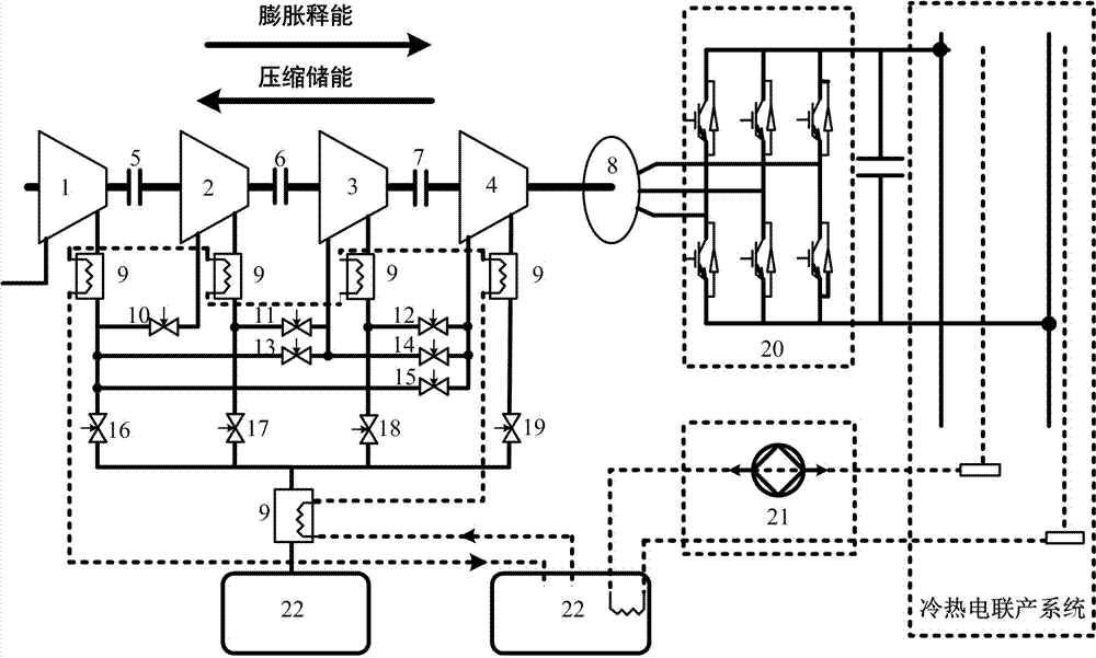
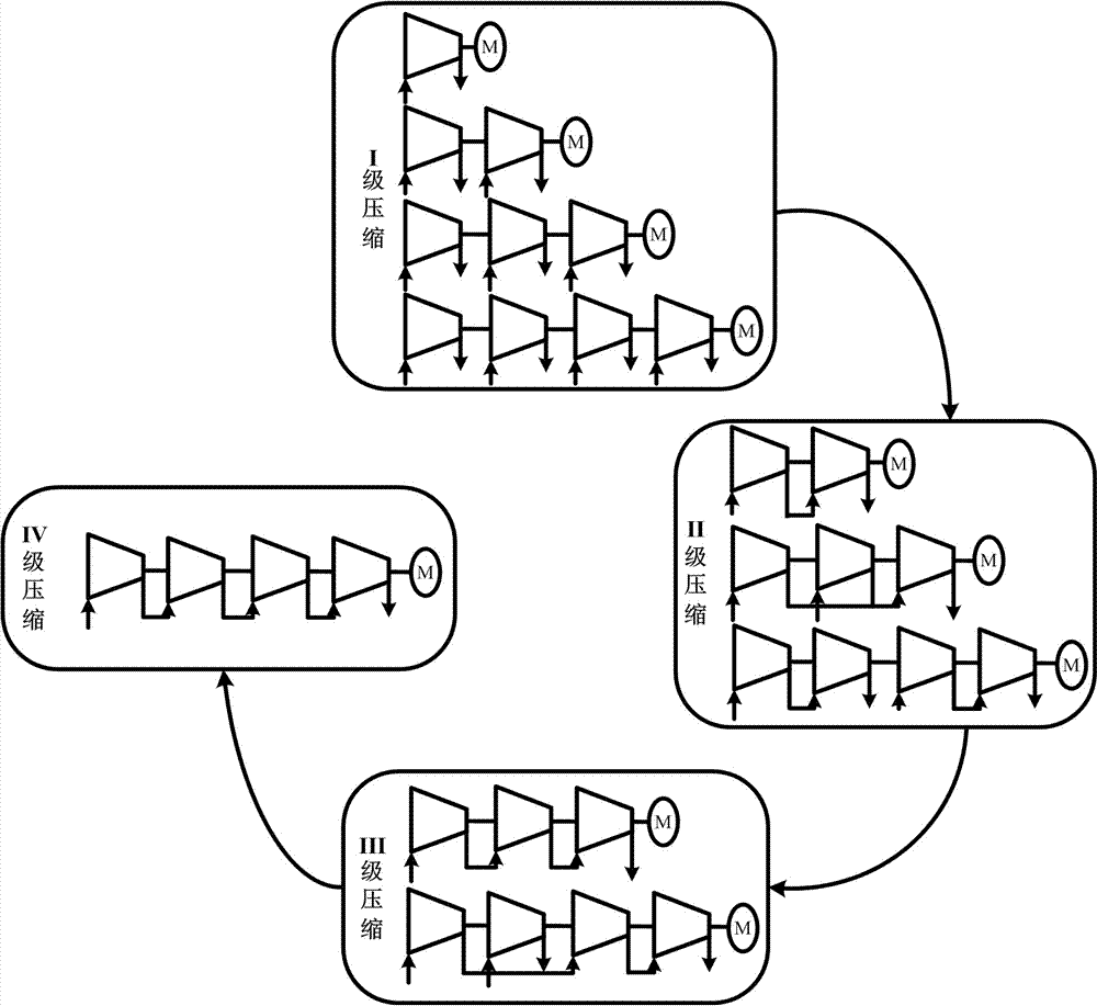
[0020] The salient feature of the present invention is that the flexible adjustment of the structure of the energy storage system can be formed through the optimized combination of the electromagnetic clutches (5-7) and the gas circuit valves (10-19), respectively. figure 2 Compression energy storage mode structure and image 3 Expansion energy release mode structure, because the air pressure of the gas tank gradually increases in the compression mode, the mechanism adjustment in the compression mode follows the single-stage to multi-stage arrows ( figure 2 ) transformation process, and at the same time, in order to reduce the impact caused by the structural adjustment, the scroll machines are coupled step by step (5-6-7); image 3 ). As for the flexible structure adjustment algorithm of the energy storage system, it is determined by Figure 4 The DS...


PUM


Abstract

The invention discloses a flexible structure-variable compressed air energy storage system with vortex machines, which is applied to a cold-thermo electric micro-grid system and provided with two electric heating connectors. The compressed air energy storage system comprises the vortex machines, clutches, air circuit valves, an air storage tank, a heat storage tank, a heat exchanger, a heat exchange pump, a permanent magnet synchronous motor and a bidirectional converter. The multiple vortex machines are optimized by the clutches and the air circuit valves to form multiple energy storage system structures which are optimally selected in combination with the air pressure of the air storage tank and the dispatching power of a micro-grid. To be specific, a series structure is determined according to the ratio of inner pressure to outer pressure of the vortex machines, and a parallel structure is determined according to the dispatching power of the micro-grid and the power of the energy storage system. According to the invention, energy generated by compression and expansion is recycled to the heat storage tank by the heat exchanger, and compression energy storage capacity is improved in combination with heat exchange between the heat exchange pump and a thermal loop of the micro-grid; the compression energy storage capacity and the short-time quickly changing fluctuating power adjusting capacity can be effectively improved, and the development of new energy industry and the optimizing and upgrading of the energy structures can be greatly promoted.

Description

technical field [0001] The invention relates to a compressed air energy storage system of a flexible variable-structure vortex machine, in particular to a compressed air energy storage system applied to a combined cooling, heating and power micro-grid system. Background technique [0002] Today, when environmental pollution, especially smog, is becoming more and more serious, new energy sources such as wind energy and solar energy are developing rapidly. According to statistics, in 2013, the proportion of new energy in global energy consumption has reached 15%, and it is growing at a rate of about 30% per year. In fact, The industrialization process of new energy is not smooth, and the large-scale grid connection of new energy has brought many challenges and safety problems to the grid security. The study found that high-efficiency energy storage equipment and its optimal control technology are the key to solving the above problems. [0003] At present, the commonly used e...

Claims


Application Information

Patent Timeline
Patent Type & Authority Applications(China)
IPC IPC(8): F04C23/02F04C23/00F01C13/00F01C11/00F25B1/00
Inventor 褚晓广张承慧蔡彬孔英
Owner QUFU NORMAL UNIV
Learn More