Lifting steel belt for elevator and elevator lifting system comprising lifting steel belt

A steel belt and elevator technology, applied in the elevator field, can solve the problems of inability to achieve slippage, increased wear of the lifting steel belt, inconsistent force, etc., to solve the problem of deviation and uneven force, reduce vibration and noise, The effect of improving the stress state

Active Publication Date: 2014-07-16
GUANGZHOU GUANGRI ELEVATOR IND
View PDF13 Cites 4 Cited by
  • Summary
  • Abstract
  • Description
  • Claims
  • Application Information

AI Technical Summary

Problems solved by technology

[0004] There are also some designs that adopt concave-convex shapes to lift the steel belt, such as Chinese patent 200810061529.9, which changes the shape of the lifting steel belt and adds a plurality of scattered discontinuous protrusions, with concave surfaces between each protrusion (or a V-ribbed belt) ), the concave-convex surface is made correspondingly on the wheel groove to match with the convex and concave surface of the lifting steel belt. Although it can also effectively realize the guiding of the lifting steel belt, the fatal flaw of this structure is that it leads to the gap between the lifting steel belt and the wheel groove. The friction coefficient is large, and the hoisting steel belt cannot slip. According to the elevator standard, no matter what reason the elevator stays in the hoistway, the steel wire rope should be allowed to slip on the sheave. This structure cannot slip, so its application is very limited
In addition, the cost of producing this kind of concave-convex shape lifting steel belt is more expensive than ordinary flat steel belt
[0005] Such as the Chinese patent application number 200780100831.4, although its two sides are also provided with arc-shaped guide surfaces, but because its arc-shaped surface is sunken to the inside of the steel strip, the thickness of the steel strip increases from the center direction to both sides, and its guide pulley It is still a traditional drum-shaped structure. The inevitable defect of the drum-shaped structure is that the force in the middle is too large and inconsistent, and the thickness of the steel strip is the smallest at the position where the force is the largest in the middle. Therefore, the middle of the steel strip is easy to cracked, and once cracked, it cannot be steered
[0006] Another example is the Chinese patent whose application number is 200810120635.X, the two sides of its steel strip are provided with a plurality of arc surfaces (each steel wire corresponds to one arc surface), this design has the same The defect is that the contact area between the steel belt and the pulley is greatly increased, resulting in a large friction coefficient, and the lifting steel belt cannot slip according to the elevator standard requirements
Furthermore, multiple arc-shaped protrusions are provided on both sides of the lifting steel belt, which requires corresponding multiple arc-shaped grooves to be set on the pulley, which requires very high machining accuracy for the pulley. The production accuracy requirements are also very high. Once the arc accuracy of the lifting steel belt and the pulley is not enough, since the lifting steel belt is composed of multiple strands of steel wire ropes and connected into one, it will lead to multi-point constraints on the lifting steel belt (each lifting steel belt Each arc-shaped protrusion is constrained by the corresponding arc-shaped groove on the pulley), resulting in an over-constrained situation, and a pull is formed between each arc-shaped protrusion, which will easily lead to increased wear of the lifting steel belt and uneven force due to uneven force. Crack

Method used


Image

  • Lifting steel belt for elevator and elevator lifting system comprising lifting steel belt
  • Lifting steel belt for elevator and elevator lifting system comprising lifting steel belt
  • Lifting steel belt for elevator and elevator lifting system comprising lifting steel belt

Examples


Embodiment 1

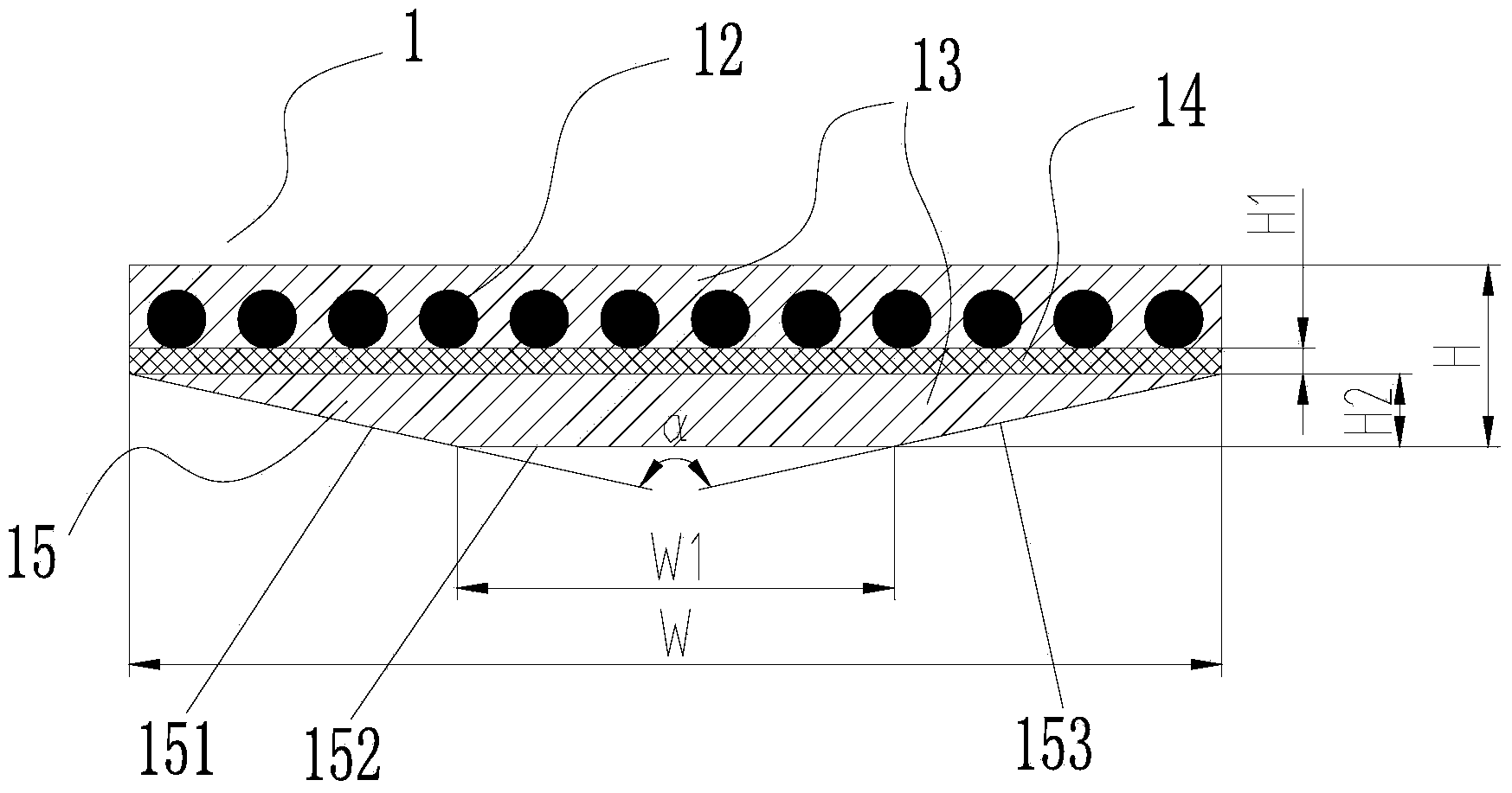
[0040] Such as figure 2 As shown, the hoisting steel belt 1 in this embodiment is composed of multi-strand steel wire ropes 12 and a wrapping layer 13 that wraps each steel wire rope 12 into one. The material of the wrapping layer 13 is polyurethane. The multi-strand steel wire ropes 12 are arranged side by side in a plane, and a reinforcement layer 14 of a mesh structure is arranged in the wrapping layer 13 on the lower side of the plane formed by the multi-strand steel wire ropes 12, and polyurethane is filled in the mesh structure of the reinforcement layer 14. The reinforcing layer 14 is made of aramid fiber material, and the thickness H1 is 0.7 mm. The mesh of the reinforcing layer 14 can be diamond-shaped, the smallest part of the mesh is not less than 3 mm, and the largest part of the mesh skeleton is not larger than 8 mm.

[0041] The lifting steel belt 1 is bounded by the steel wire rope 12, and the side corresponding to the reinforcement layer 14, which is the rev...

Embodiment 2

[0044] Such as Figure 4 As shown, the guide protrusion 15 of the lifting steel belt 1 of the present embodiment is composed of a left guiding surface 151, a central guiding surface 152 and a right guiding surface 153 connected in sequence, and the width W1 of the central guiding surface 152 is smaller than the width W1 of the entire lifting steel belt 12. W, and the left guide surface 151 and the right guide surface 153 are arranged symmetrically, the central guide surface 152 is a plane, and the left guide surface 151 and the right guide surface 153 are convex arc surfaces (the radius R of the arc surface can be 21.25mm), forming The cross-section of the guide protrusion 15 is close to an isosceles trapezoid. Others are the same as embodiment 1.

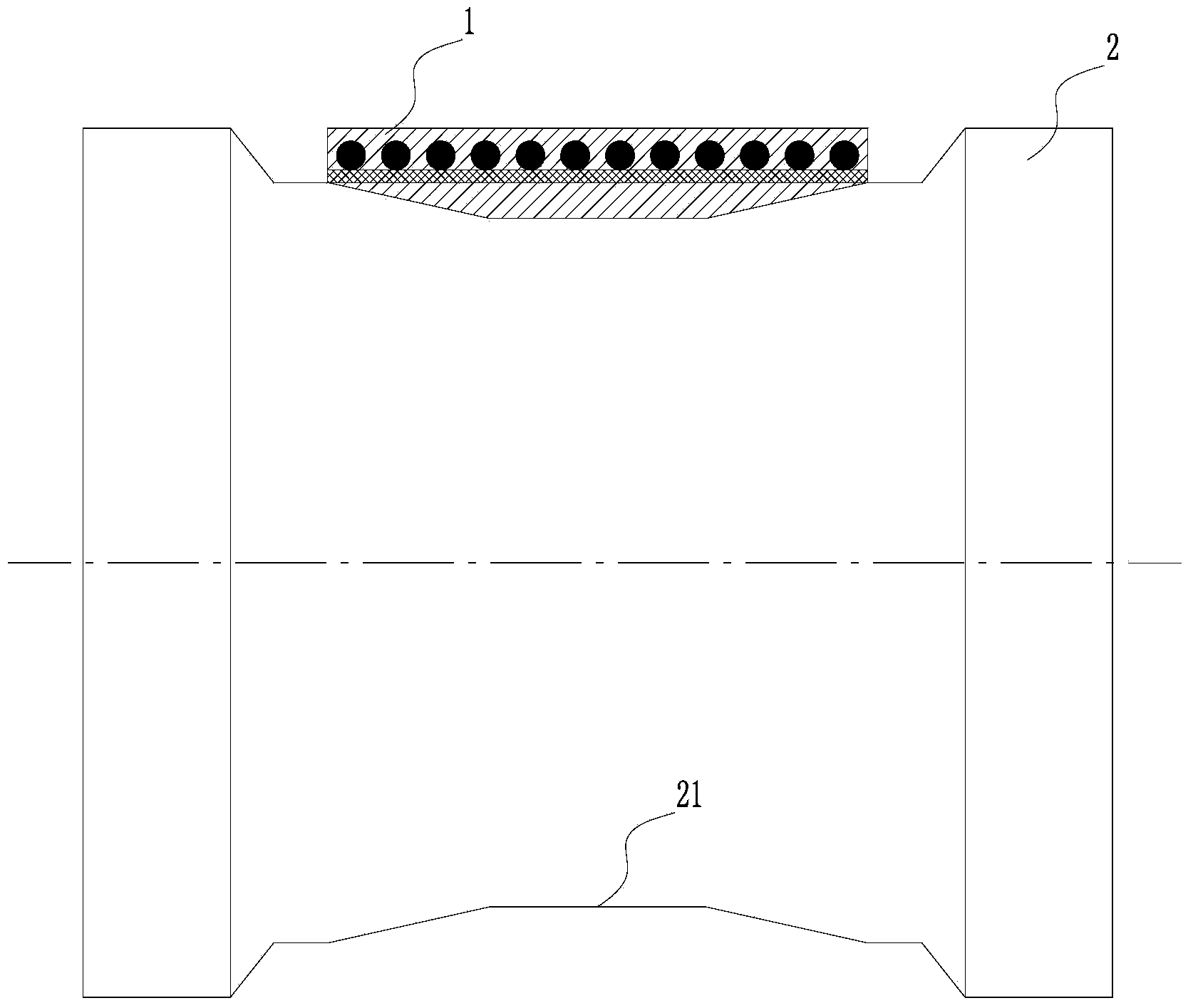
[0045] Such as Figure 5 As shown, the pulley 2 used in conjunction with the lifting steel belt 1 of this embodiment is provided with a guide groove 21 matching the shape and size of the guide protrusion 15 .

Embodiment 3

[0047] Such as Figure 6 As shown, the guide protrusion 15 of the lifting steel belt 1 of the present embodiment is composed of a left guiding surface 151, a central guiding surface 152 and a right guiding surface 153 connected in sequence, and the width W1 of the central guiding surface 152 is smaller than the width W1 of the entire lifting steel belt 12. W, and the left guide surface 151 and the right guide surface 153 are arranged symmetrically, the central guide surface 152 is a convex arc surface (the radius R of the arc surface can be 21.25mm), and the left guide surface 151 and the right guide surface 153 are planes, forming The cross-section of the guide protrusion 15 is close to an isosceles trapezoid. Others are the same as embodiment 1.


PUM


Abstract

The invention discloses a lifting steel belt for an elevator and an elevator lifting system comprising the lifting steel belt. The lifting steel belt comprises a plurality of steel wire rope strands and a wrapping layer which wraps the steel wire ropes integrally. A net-shaped structure reinforcing layer is arranged in the wrapping layer on at least one of the upper side and the lower side of the steel wire ropes. The net-shaped structure of the reinforcing layer is filled with wrapping layer materials. Due to the added net-shaped reinforcing layer, the anti-tearing strength of the steel belt is greatly improved, the problem that the middle portion of a flat steel belt can be cracked easily is avoided, and service life is greatly prolonged.

Description

technical field [0001] The invention relates to the field of elevators, in particular to a hoisting steel belt capable of realizing the hoisting function. The hoisting steel belt is mainly used as an elevator traction, bearing, suspension and hoisting component. Background technique [0002] Traditional elevators mainly use steel wire ropes as the carrier for traction and suspension. The steel wire rope is not only used as a safety component to carry the weight of the car and counterweight, but also as a carrier for traction to drive the elevator car to run up and down. Steel wire rope has been used as an important part of elevators for many years, but its disadvantages are also very obvious. Steel wire rope has the disadvantages of large amount of steel, easy wear, uneven force, lubrication, rust, troublesome maintenance, and high installation requirements. In the prior art, V-shaped belt slits and U-shaped belt slits are often used to increase the traction capacity, but th...

Claims


Application Information

Patent Timeline
Patent Type & Authority Applications(China)
IPC IPC(8): F16G9/00B66B11/08
Inventor 贺云朗侯应浩
Owner GUANGZHOU GUANGRI ELEVATOR IND
Why Eureka
Try Eureka