Self-priming burner

A burner, self-priming technology, applied in burners, gas fuel burners, combustion methods, etc., can solve the problems of difficult flame adjustment, inconvenient use, narrow application range, etc. Well-designed effects

Inactive Publication Date: 2014-07-16
WEIHAI SHIDAO HEAVY IND
View PDF6 Cites 5 Cited by
  • Summary
  • Abstract
  • Description
  • Claims
  • Application Information

AI Technical Summary

Problems solved by technology

[0003] In order to overcome the disadvantages of flame adjustment difficulty, low combustion efficiency, inconvenient use and narrow application range of the existing publicly used burners, the present invention provides a burner with reasonable design, simple and compact structure, convenient use, wide range of gas use, and high thermal efficiency. tall self-priming burner

Method used


Image

  • Self-priming burner
  • Self-priming burner
  • Self-priming burner

Examples


Embodiment Construction

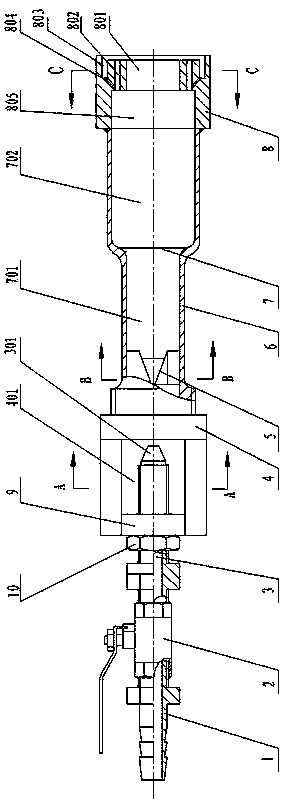
[0015] exist figure 1 Among them, a self-priming burner includes a body 6 , a gas connecting pipe 1 , a valve 2 , a gas nozzle 3 and a combustion nozzle 8 .

[0016] Such as figure 1 As shown, the valve 2 is installed between the gas connection pipe 1 and the gas nozzle 3 to control the connection or closure of the gas.

[0017] exist figure 1 Among them, the interior of the body 6 is opened with a through injection cavity 7 .

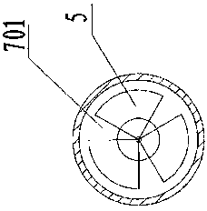
[0018] Such as figure 1 As shown, the injection cavity 7 is composed of a first injection cavity 701 and a second injection cavity 702 , wherein the cross-sectional area of ​​the second injection cavity 702 is larger than that of the first injection cavity 701 . According to the entry path of the mixed gas, the cross-sectional area of ​​the gas channel changes from small to large, so that the mixed gas entering the second injection cavity 702 can be mixed again.

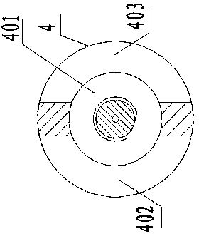
[0019] exist figure 1 Among them, a gas regulating seat 4 is installed on the begin...


PUM


Abstract

The invention relates to a self-priming burner which comprises a burner body, a fuel gas connecting pipe, a valve, a fuel gas spraying pipe and a burner nozzle. The valve is installed between the fuel gas connecting pipe and the fuel gas spraying pipe. A through injection chamber is formed in the burner body. The burner nozzle is installed at the tail end of the burner body. The self-priming burner is characterized in that a fuel gas adjusting base with a fuel gas preliminary mixing chamber is installed at the starting end of the burner body, two air induction openings communicated with the fuel gas preliminary mixing chamber are symmetrically formed in a base body, the fuel gas spraying pipe is installed on a spraying pipe installation piece of the fuel gas adjusting base, and a nozzle of the fuel gas spraying pipe stretches into the fuel gas preliminary mixing chamber; three spiral-flow-type mixing blades are arranged in the injection chamber; the end of the burner nozzle is provided with a central gas outlet communicated with a gas outlet chamber, a plurality of parallel gas outlets and an annular gas outlet groove. The self-priming burner has the advantages of being capable of saving energy, adjustable, high in burning efficiency, low in fuel gas inlet pressure requirement and wide in gas application range. The self-priming burner is particularly suitable for natural gas.

Description

technical field [0001] The invention relates to a burner for burning gas fuel, in particular to a self-priming burner suitable for heat treatment during welding of pressure vessels. Background technique [0002] In the production process of pressure vessels, in order to ensure the welding quality of pressure vessels, it is often necessary to heat the welded parts. The general heat treatment method is: use combustible gas as a fuel burner for heat treatment. At present, this type of publicly used combustible gas burner mainly includes a body provided with a mixing chamber, a gas inlet pipe and a high-pressure air inlet pipe installed on the body and communicated with the mixing chamber, and a gas inlet pipe arranged at the end of the body and connected to the The combustible gas burner with this structure has the following problems: firstly, the combustion efficiency is low; secondly, it is difficult to adjust the flame; thirdly, it is inconvenient to use. For external powe...

Claims


Application Information

Patent Timeline
Patent Type & Authority Applications(China)
IPC IPC(8): F23D14/04F23D14/58F23D14/64
Inventor 范伟军阎峻青隋进花马运水王明鹏宋占祺
Owner WEIHAI SHIDAO HEAVY IND
Why Eureka
Try Eureka