Device and method for measuring frequency response of high-speed photodetector

A photoelectric detector and frequency response testing technology, which is applied in the direction of measuring devices, measuring electricity, and measuring electrical variables, etc., can solve the problems of large rated error, inaccurate measurement results, and large frequency response error of photoelectric detectors.

Active Publication Date: 2016-06-08
UNIV OF ELECTRONICS SCI & TECH OF CHINA
View PDF5 Cites 0 Cited by
  • Summary
  • Abstract
  • Description
  • Claims
  • Application Information

AI Technical Summary

Problems solved by technology

[0005] In order to solve the frequency response measurement of high-speed photodetectors by the frequency sweep test method, because the vector network analyzer can only measure the frequency response of the detector lower than its test frequency, and the influence of the frequency response of the modulator cannot be ignored, it is necessary to separately analyze the frequency response of the used modulation Calibration of high-speed photoelectric detectors, the problem of expensive test equipment; the problem of large rated error and low measurement accuracy of optical pulse spectrum analysis method in the frequency response measurement process of high-speed photoelectric detectors; interference frequency modulation sideband spectrum analysis method in high-speed photoelectric detection In the process of measuring the frequency response of the photodetector, due to the instability of high-order FM sidebands caused by small current modulation, the measurement results are inaccurate; the optical heterodyne method is used in the measurement of the frequency response of high-speed photodetectors due to the random phase noise of the two laser beams. The impact causes the line width of the beat frequency signal to be wide, making the measurement system unstable, and the problem of large error when measuring the frequency response of the photodetector; and providing a device and method for measuring the frequency response of a high-speed photodetector with self-calibration capability, Accurate Measurement of High-Speed ​​Photodetector Frequency Response

Method used


Image

  • Device and method for measuring frequency response of high-speed photodetector
  • Device and method for measuring frequency response of high-speed photodetector
  • Device and method for measuring frequency response of high-speed photodetector

Examples


Embodiment 1

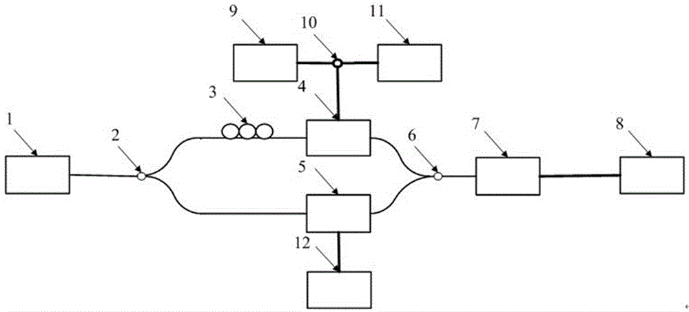
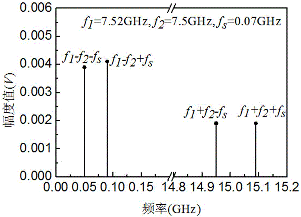
[0056] The photodetector to be tested uses HP11982A, and the frequency f of the laser 1 output light 0=193.1THz, taking one of the measurement frequency points as an example, the frequency f output by the first signal source 9 1 =7.52GHz sinusoidal signal and the frequency f of the output of the second signal source 11 2 The sinusoidal signal of =7.5GHz forms two-tone sinusoidal signal and enters phase modulator 4 by combiner 10, the frequency f of the 3rd signal source 12 outputs s =0.07GHz sinusoidal signal, the frequency in the output signal of the optical fiber interferometer under the above three kinds of sinusoidal signal effects is 0.05GHz (f 1 -f 2 -f s ), 0.09GHz (f 1 -f 2 +f s ), 14.95GHz (f 1 +f 2 -f s ), 15.09GHz (f 1 +f 2 +f s ) magnitude, respectively denoted as i(f 1 -f 2 -f s ), i(f 1 -f 2 +f s ), i(f 1 +f 2 -f s ), i(f 1 +f 2 +f s ); figure 2 In this embodiment, the method for measuring the frequency response of the high-speed photode...

Embodiment 2

[0062] The photodetector to be tested uses PicometrixP-20A, taking one of the measurement frequency points as an example, the frequency f of laser 1 output light 0 =193.4THz, the frequency f of the output of the first signal source 9 1 =9.53GHz sinusoidal signal and the frequency f of the output of the second signal source 11 2 The sinusoidal signal of =9.5GHz forms two-tone sinusoidal signal and enters phase modulator 4 by combiner 10, the frequency f of the 3rd signal source 12 outputs s =0.1GHz sinusoidal signal, the frequency in the output signal of the optical fiber interferometer under the above three kinds of sinusoidal signal effects is 0.07GHz (f 1 -f 2 -f s ), 0.13GHz (f 1 -f 2 +f s ), 18.93GHz (f 1 +f 2 -f s ), 19.13GHz (f 1 +f 2 +f s ) magnitude, respectively denoted as i(f 1 -f 2 -f s ), i(f 1 -f 2 +f s ), i(f 1 +f 2 -f s ), i(f 1 +f 2 +f s ); Figure 4 In this embodiment, the method for measuring the frequency response of the high-speed p...

Embodiment 3

[0068] The photodetector to be tested uses PicometrixPT-40A, taking one of the measurement frequency points as an example, the frequency f of the output light of laser 1 0 =193.411THz, the frequency f output by the first signal source 9 1 =19.57GHz sinusoidal signal and the frequency f of the output of the second signal source 11 2 The sinusoidal signal of =19.5GHz forms two-tone sinusoidal signal and enters phase modulator 4 by combiner 10, the frequency f of the 3rd signal source 12 outputs s =0.12GHz sinusoidal signal, the frequency in the output signal of the optical fiber interferometer under the above three kinds of sinusoidal signal effects is 0.05GHz (f 1 -f 2 -f s ), 0.19GHz (f 1 -f 2 +f s ), 38.95GHz (f 1 +f 2 -f s ), 39.19GHz (f 1 +f 2 +f s ) magnitude, respectively denoted as i(f 1 -f 2 -f s ), i(f 1 -f 2 +f s ), i(f 1 +f 2 -f s ), i(f 1 +f 2 +f s ); Image 6 In this embodiment, the method for measuring the frequency response of the high-sp...


PUM


Abstract

The invention provides a frequency response measuring device and method of a high-speed photoelectric detector, and the frequency response measuring device and method of the high-speed photoelectric detector are used for solving the problem that an existing frequency response test of the high-speed photoelectric detector is not accurate. The frequency response measuring device comprises a first signal source, a second signal source, a third signal source and an optical fiber interferometer. The optical fiber interferometer is composed of a beam splitter, a polarization controller, a phase modulator, an acousto-optic frequency shifter and a beam combiner. The polarization controller and the phase modulator are connected with one interference arm of the optical fiber interferometer in series. The acousto-optic frequency shifter is placed on the other interference arm of the optical fiber interferometer. The beam splitter and the beam combiner are connected to the two ends of the two interference arms respectively in series. A light path of the beam splitter is connected with a laser. A light path of the beam combiner is connected with the high-speed photoelectric detector to be detected. The high-speed photoelectric detector to be detected is in circuit connection with a sampling circuit used for recording and analyzing. The first signal source and the second signal source are in circuit connection with an electrode of the phase modulator through a combiner. The third signal source is electrically connected with the electrode of the acousto-optic frequency shifter.

Description

technical field [0001] The invention belongs to the field of high-speed photodetectors in optoelectronic technology, and in particular relates to a frequency response measuring device and method for high-speed photodetectors. Background technique [0002] Photodetectors are the basic components of optical transmission and optical signal processing systems. Photodetectors convert optical signals into electrical signals with instantaneous and high sensitivity, and play an indispensable role in high-speed optical fiber communication and coherent optical communication systems. [0003] The frequency response of the photodetector is one of the important characteristic parameters of the photodetector, which reflects the response ability to convert the optical carrier of different modulation frequencies into electrical signals. It is of great significance to reduce the bit error rate. [0004] At present, the methods for measuring the frequency response of photodetectors are gener...

Claims


Application Information

Patent Timeline
Patent Type & Authority Patents(China)
IPC IPC(8): G01R31/00
Inventor 张尚剑王恒邹新海尹欢欢陈沫张雅丽刘永
Owner UNIV OF ELECTRONICS SCI & TECH OF CHINA
Why Eureka
Try Eureka