Method and system for testing OLED display device

A technology for display devices and testing methods, applied in photometry, static indicators, electrical solid devices, etc., can solve problems such as restricting the testing and repairing of OLED backplane finished products, limited accuracy, data analysis, etc., to improve testing efficiency. and test intuitiveness, reducing the effect of test cost

Inactive Publication Date: 2014-07-16
BOE TECH GRP CO LTD
View PDF5 Cites 12 Cited by
  • Summary
  • Abstract
  • Description
  • Claims
  • Application Information

AI Technical Summary

Problems solved by technology

However, compared with the LCD backplane testing technology, the OLED backplane cannot be tested by liquid crystal simulation. In the prior art, the secondary electron imaging test method and the electrical test method are usually used to test the OLED backplane. Among them, two The accuracy of the sub-electronic imaging test method is limited, while the electrical test method has too high requirements on the design and process of the OLED backplane, and at the same time requires data analysis and is not intuitive enough
[0003] Due to the various defects of the OLED backplane test method in the prior art, the finished product test and subsequent repair process of the OLED backplane are greatly restricted.

Method used


Image

  • Method and system for testing OLED display device
  • Method and system for testing OLED display device
  • Method and system for testing OLED display device

Examples


Embodiment 1

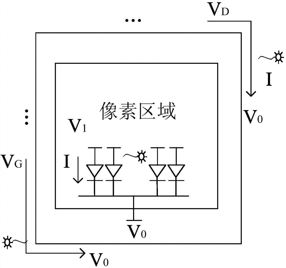
[0101] Example 1: The OLED display device to be tested is an AMOLED-IGZO-TFT backplane with a 2T1C structure

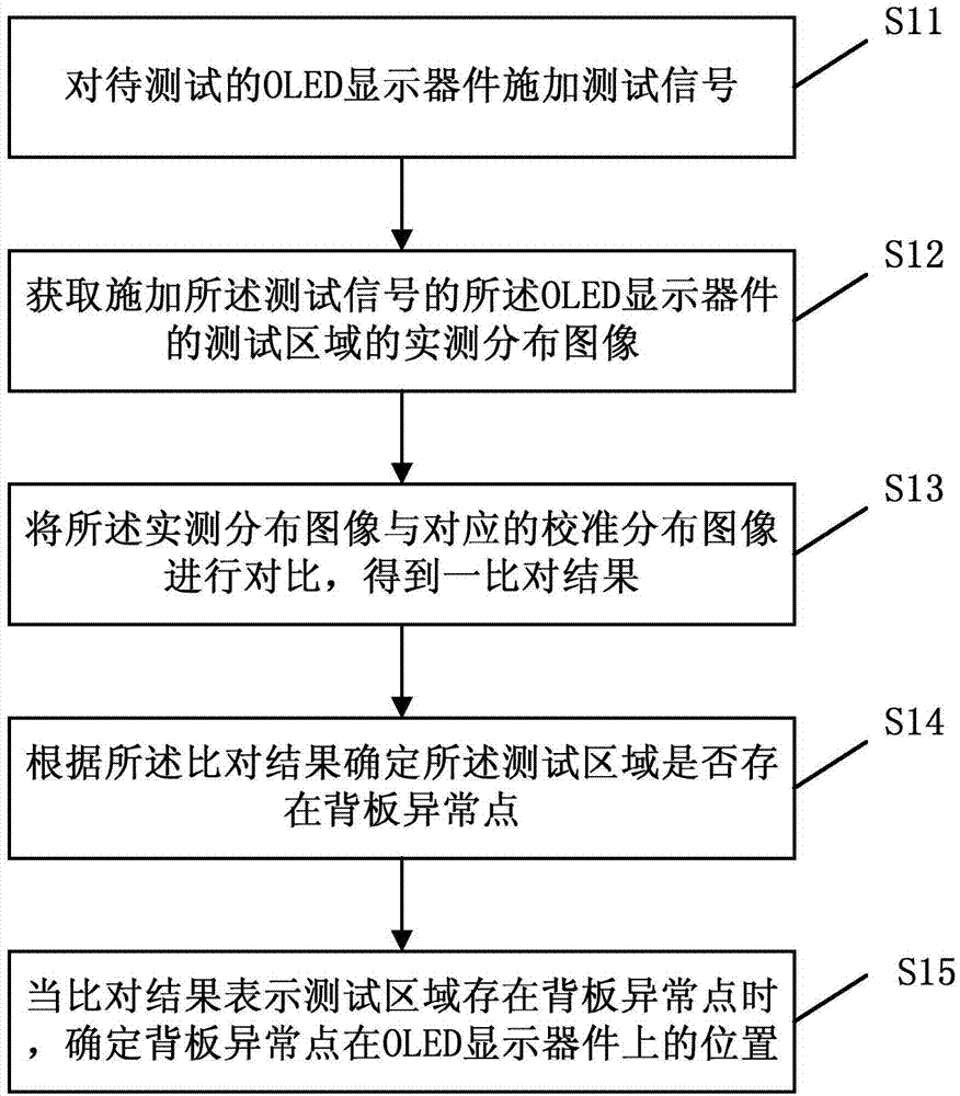
[0102] The testing method of the OLED display device according to Embodiment 1 of the present invention comprises the following steps:

[0103] Step S21: placing the to-be-tested IGZO-TFT backplane that has completed the array substrate (Array) process on the test platform;

[0104] Step S22: using a photon-sensing infrared CCD imager to capture the alignment mark (Mark) of the IGZO-TFT backplane, and align the position of the IGZO-TFT backplane according to the alignment mark.

[0105] Step S23: After aligning the position, attach an OLED circuit simulation board on the IGZO-TFT backplane, after the circuit simulation board is bonded to the IGZO-TFT backplane, the IGZO-TFT backplane The circuit elements are connected with the circuit elements on the OLED circuit simulation board to form a test loop. A photon-sensing infrared CCD imager is used to scan and move from...

Embodiment 2

[0109] Embodiment 2: The OLED display device to be tested is an AMOLED-LTPS-TFT backplane with a 4T2C structure including a compensation circuit

[0110] The testing method of the OLED display device of the second embodiment of the present invention comprises the following steps:

[0111] Step S31: placing the to-be-tested LTPS-TFT backplane on which the array substrate process has been completed on the test platform;

[0112] Step S32: Using a photon-sensing infrared CCD imager to capture the alignment mark on the LTPS-TFT backplane, and align the position of the LTPS-TFT backplane according to the alignment mark.

[0113]Step S33: After aligning the position, attach an OLED circuit simulation board on the LTPS-TFT backboard, and after the OLED circuit simulation board is bonded to the LTPS-TFT backboard, the LTPS-TFT backboard The circuit elements are connected with the circuit elements on the OLED circuit simulation board to form a test loop. A photon-sensing infrared CCD...


PUM


Abstract

The invention provides a method and system for testing an OLED display device. The method comprises the step of exerting a test signal on the OLED display device to be tested, the step of obtaining an actual measurement distribution image of the testing area of the OLED display device on which the test signal is exerted, the step of comparing the actual measurement distribution image with a corresponding calibration distribution image to obtain a comparison result, and the step of determining whether a backboard abnormal point exists in the testing area or not according to the comparison result, wherein when the comparison result shows that the backboard abnormal point exists in the testing area, the position of the backboard abnormal point on the OLED display device is determined. According to the method and system for testing the OLED display device, testing efficiency and testing visuality of the OLED display device can be improved, and testing cost is reduced.

Description

technical field [0001] The invention relates to the field of testing OLED display devices, in particular to a testing method and a testing system for OLED display devices. Background technique [0002] AMOLED (Organic Light Emitting Diode) panel is recognized as the core technology of next-generation display. Its preparation is similar to that of LCD (Liquid Crystal Display), and it also needs to test the TFT (Thin Film Transistor) backplane. However, compared with the LCD backplane testing technology, the OLED backplane cannot be tested by liquid crystal simulation. In the prior art, the secondary electron imaging test method and the electrical test method are usually used to test the OLED backplane. Among them, two The accuracy of the sub-electronic imaging test method is limited, while the electrical test method has too high requirements on the design and process of the OLED backplane, and at the same time requires data analysis and is not intuitive enough. [0003] Due ...

Claims


Application Information

Patent Timeline
Patent Type & Authority Applications(China)
IPC IPC(8): G09G3/00
CPCG01J2001/4247G01J5/0066G09G3/32G09G2320/0295G09G2330/10G09G2360/147G09G3/006G01J5/48H10K71/70
Inventor 李延钊王刚方金钢赵会查奇君
Owner BOE TECH GRP CO LTD
Why Eureka
Try Eureka