Ultrathin electromagnetic steel sheet

A kind of electromagnetic steel plate, ultra-thin technology, applied in the direction of thin material processing, inorganic material magnetism, ultra-thin film/granular film, etc., can solve the problems of difficult high-Si steel plate, processability deterioration, etc., to achieve stable magnetic properties and avoid magnetic properties effect of degradation and reduction of the duty cycle

Active Publication Date: 2014-07-16
JFE STEEL CORP
View PDF8 Cites 7 Cited by
  • Summary
  • Abstract
  • Description
  • Claims
  • Application Information

AI Technical Summary

Problems solved by technology

However, if the amount of Si in the steel sheet exceeds 3.5% by mass, the workability will significantly deteriorate, so it is difficult to manufacture such a high-Si steel sheet by rolling as a conventional manufacturing method of electrical steel sheets.

Method used


Image

  • Ultrathin electromagnetic steel sheet
  • Ultrathin electromagnetic steel sheet
  • Ultrathin electromagnetic steel sheet

Examples


Embodiment 1

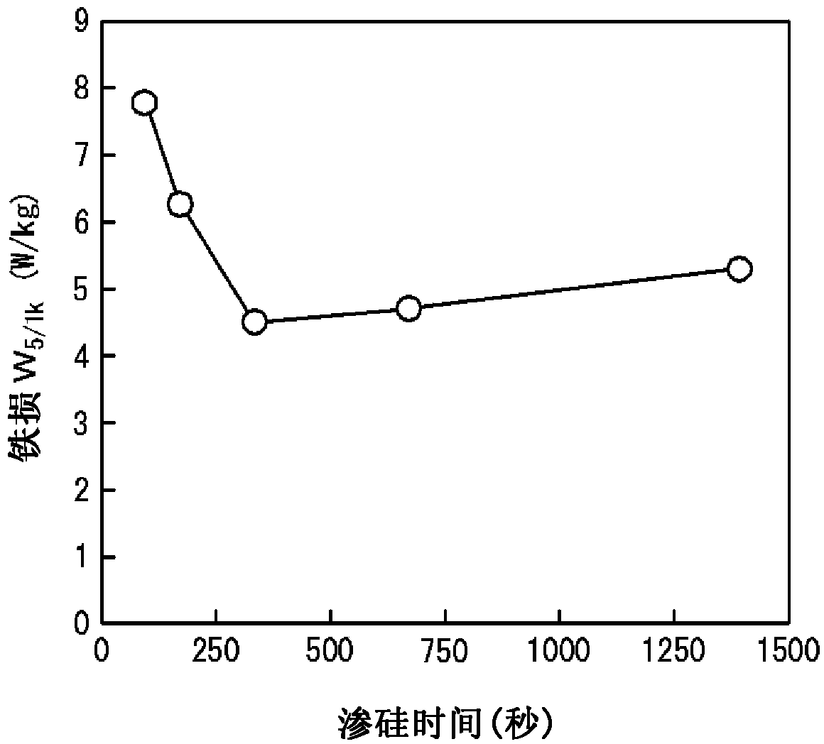
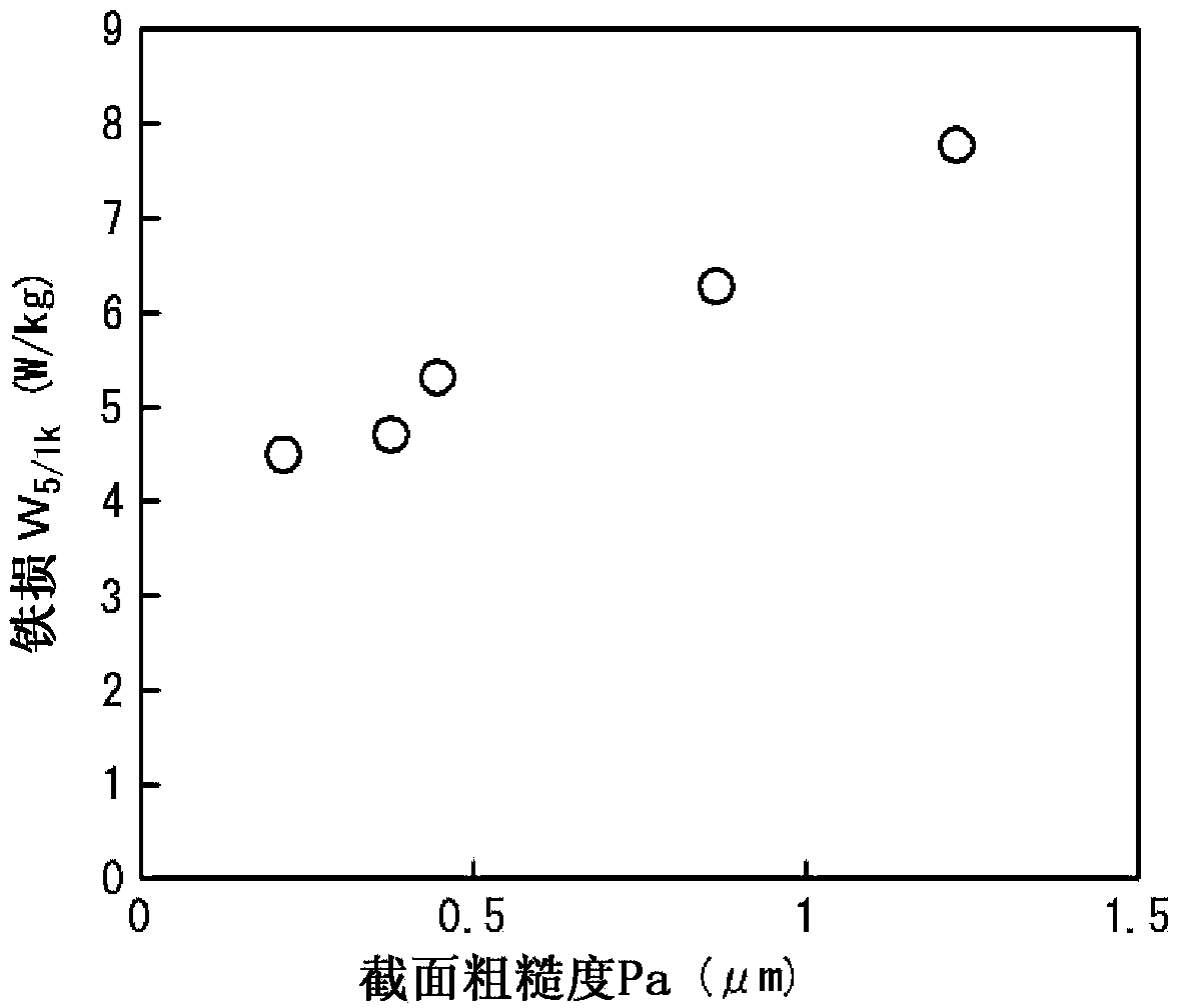
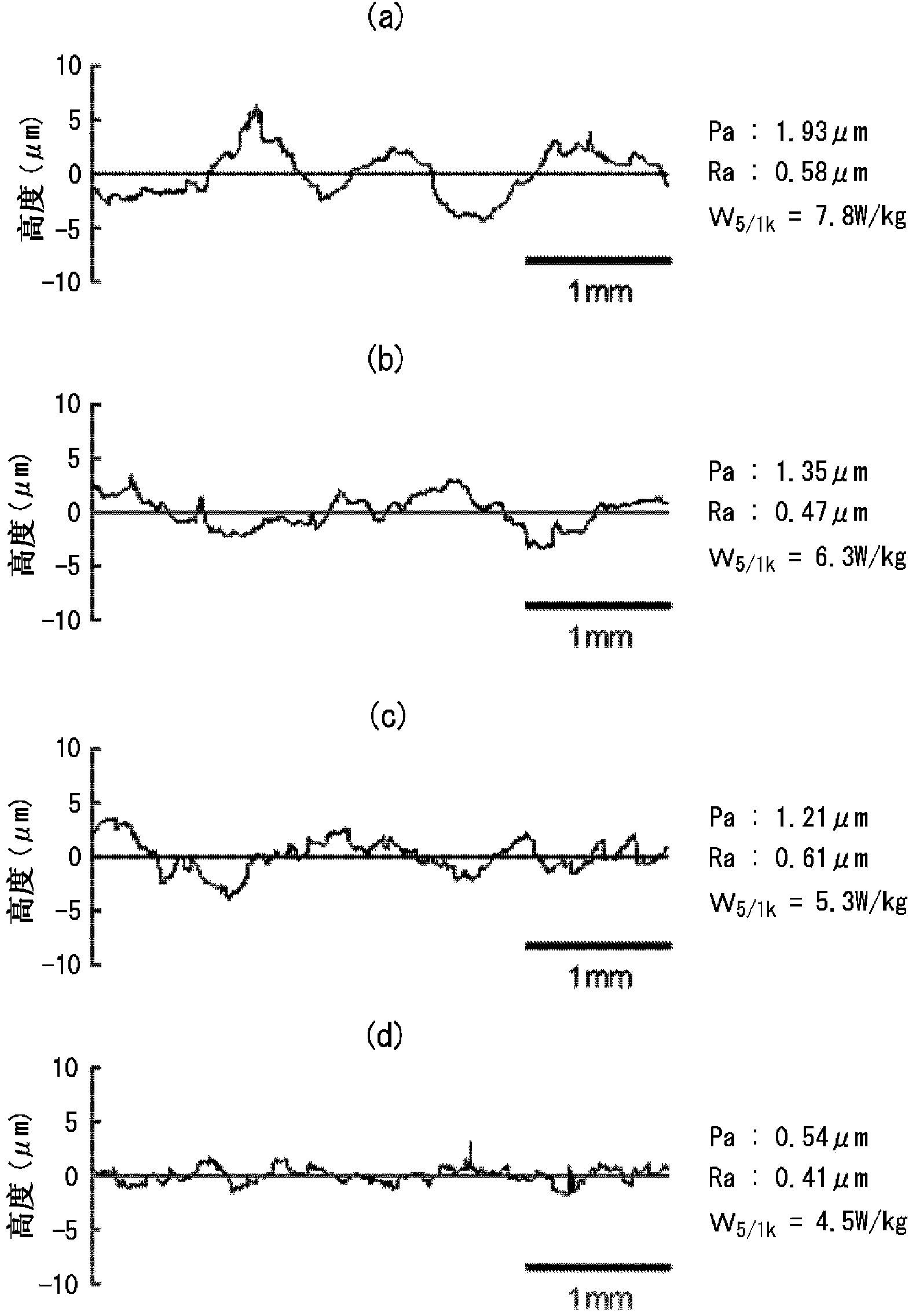
[0085] A steel billet containing C: 0.0031%, Si: 3.05%, and Mn: 0.15% is produced by continuous casting, and the balance is composed of Fe and unavoidable impurities. rolling plate. Next, the hot-rolled sheet was annealed at 1000° C. for 30 seconds, then cold-rolled to a sheet thickness of 0.075 mm, and then rolled in (10% SiCl 4 +90% Ar) atmosphere at 1100° C. for 600 seconds of siliconizing treatment. At this time, in the annealing furnace, such as Figure 4 As shown in (a), it is installed in such a way that intermittent siliconizing treatment can be performed. Two or more nozzles 1 for injecting raw material gas are arranged near both surfaces of the steel plate 2, and a pair of nozzles 1 for shielding raw material gas are arranged between the nozzles. The shielding plates 3 can be siliconized by raw material gas in the vicinity of the injection nozzle 1 without siliconizing between the shielding plates 3 . Moreover, for some samples, such as Figure 4 As shown in (b),...

Embodiment 2

[0093] Steel slabs having various compositions shown in Table 2 were produced by continuous casting, heated at 1200° C., and then hot-rolled into 2.7 mm hot-rolled sheets. Next, the hot-rolled sheet was annealed at 900° C. for 30 seconds, then cold-rolled to a sheet thickness of 0.050 mm, and then rolled in (15% SiCl 4 +85%N 2 ) in an atmosphere at 1200° C. for 100 seconds of siliconizing treatment. At this time, in the annealing furnace, such as Figure 4 As shown in (a), it is installed in such a way that intermittent siliconizing treatment can be performed. Two or more nozzles 1 for injecting raw material gas are arranged near both surfaces of the steel plate 2, and a pair of nozzles 1 for shielding raw material gas are arranged between the nozzles. The shielding plates 3 can be siliconized by raw material gas in the vicinity of the injection nozzle 1 without siliconizing between the shielding plates 3 . In addition, at this time, the line tension at the time of passing ...


PUM

PropertyMeasurementUnit
thicknessaaaaaaaaaa
thicknessaaaaaaaaaa
radiusaaaaaaaaaa

Abstract

By producing a composition comprising, by mass%, 0.007% or less of C, 4 to 10% of Si, and 0.005 to 1.0% of Mn, with Fe and inevitable impurities as the balance, and by bringing the sheet thickness to between 0.01 and 0.10 mm and the cross section roughness Pa to 1.0 [mu]m or less, there is no degradation of magnetic properties and it is possible to realize iron loss properties such that degradation of the space factor is avoided, even when an electromagnetic steel sheet having a sheet thickness of 0.10 mm or less has been subjected to siliconizing in order to increase the Si content of the steel.

Description

technical field [0001] The present invention relates to an extremely thin electrical steel sheet suitable for use in reactors and the like. Background technique [0002] As we all know, the iron loss of electromagnetic steel plate usually increases sharply with the increase of excitation frequency. However, the reality is that the driving frequency of transformers and reactors is increasing to increase the size and efficiency of iron cores. [0003] Therefore, the iron loss of the electrical steel sheet increases, and heat generation becomes a problem more and more often. [0004] It is well known that in order to reduce the iron loss of an electrical steel sheet, it is effective to increase the intrinsic resistance by increasing the Si content. However, if the amount of Si in the steel sheet exceeds 3.5% by mass, the workability is significantly deteriorated, so it is difficult to manufacture such a high-Si steel sheet by rolling, which is a conventional method for manufa...

Claims


Application Information

Patent Timeline
Patent Type & Authority Applications(China)
IPC IPC(8): C22C38/00B21B3/02C22C38/04C22C38/60H01F1/16C21D8/12
CPCC21D8/1222C21D8/1233C21D8/1261C21D8/1266C22C38/00C22C38/04C22C38/60H01F1/16C22C38/002C22C38/004C22C38/008C22C38/02C22C38/06C22C38/12C21D8/0263C21D1/74C21D1/76C21D6/008C21D8/1255C21D9/46C23C10/08Y10T428/12431H01F10/007
Inventor 今村猛高岛稔平谷多津彦
Owner JFE STEEL CORP
Why Eureka
Try Eureka