Arrangement of an air supply device on a cylinder head for an internal combustion engine

A technology for arrangement structure and air supply, applied in the direction of combustion air/combustion-air treatment, fuel air intake, internal combustion piston engine, etc., can solve packaging problems and other problems, achieve compact structure space, short response time, and save structure effect of space

Inactive Publication Date: 2014-07-16
DAIMLER AG
View PDF18 Cites 1 Cited by
  • Summary
  • Abstract
  • Description
  • Claims
  • Application Information

AI Technical Summary

Problems solved by technology

[0005] The known arrangement has an undesirably high installation space requirement, which leads to packaging problems especially in areas where space is at a premium, such as in the engine compartment of a motor vehicle

Method used


Image

  • Arrangement of an air supply device on a cylinder head for an internal combustion engine
  • Arrangement of an air supply device on a cylinder head for an internal combustion engine

Examples


Embodiment Construction

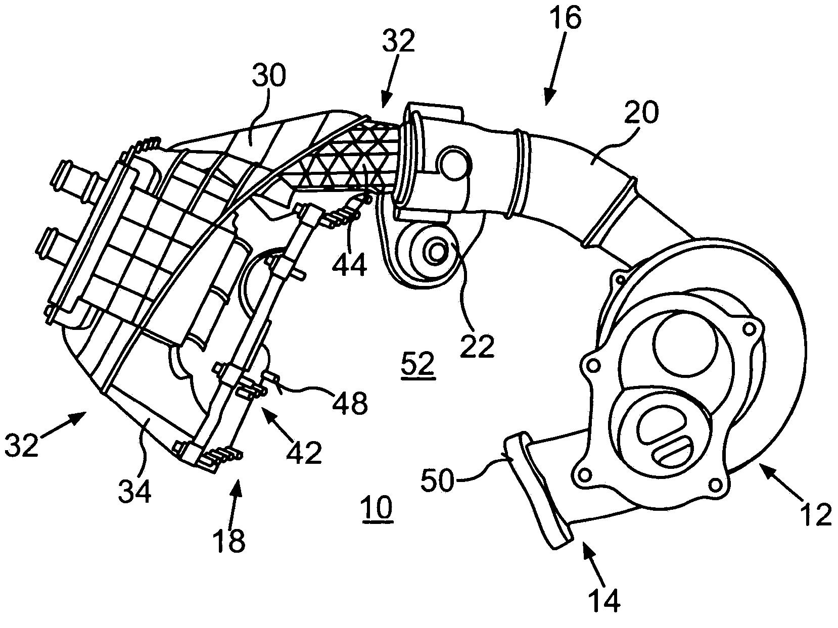
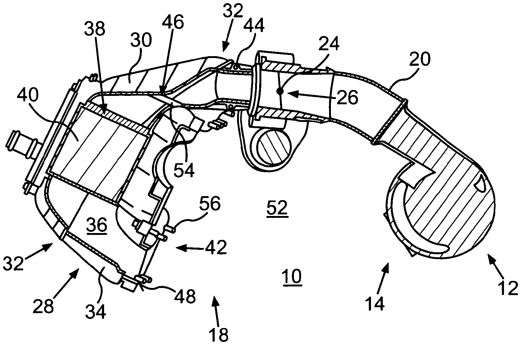
[0029] figure 1 and figure 2 shows an air supply device 10 which is arranged, for example, on a cylinder head of an internal combustion engine designed as a reciprocating piston internal combustion engine. here, figure 1 and figure 2 The air supply device 10 is shown in its assembled position, in which it is at least substantially in its state connected to or held on the cylinder head.

[0030] The air supply device 10 includes a compressor 12 of an exhaust gas turbocharger. The air to be supplied to the internal combustion engine is compressed by means of a compressor 12 . To drive the compressor 12 , the exhaust gas turbocharger comprises a turbine that can be driven by the exhaust gas of the internal combustion engine.

[0031] In order to be able to advantageously supply the turbine with exhaust gas, the exhaust gas turbocharger and thus the compressor 12 are arranged at figure 1 and figure 2 On the exhaust side 14 of the cylinder head, not shown. On the exhaust...


PUM


Abstract

The invention relates to an arrangement of an air supply device (10) on a cylinder head for an internal combustion engine, in particular of a motor vehicle. In said arrangement, the air supply device (10) comprises an intake system (28) for distributing air that is to be supplied to the internal combustion engine to combustion chambers of said engine and a compressor (12) for compressing the air, the compressor being fluidically connected to the intake system (28) via an air conduit element (16). The air supply device (10) that is held on the cylinder head extends above the cylinder head from the intake system (28) located on an air side (18) of the cylinder head via the air conduit element (16) to the compressor (12) located on an exhaust gas side (14) of the cylinder head and forms an intermediate area (52) that is delimited by the intake system (28), air conduit element (16) and the compressor (12), at least part of the cylinder head being located in said area.

Description

technical field [0001] The invention relates to an arrangement of an air supply device on a cylinder head for an internal combustion engine according to the preamble of claim 1 . Background technique [0002] DE 44 03 219 A1 discloses an intake / intake module for a multi-cylinder internal combustion engine which can be prefabricated as a structural unit, in which an injection valve is integrated which can be flanged to the cylinder head of the internal combustion engine and has a separate housing with a lower part, an upper part sealingly connected to the lower part, and at least one air inlet. The air inlet is connected via an air intake channel to a plurality of air ducts with outlet openings. For injecting fuel, the injection valve is arranged in the air line adjacent to the outlet opening of the air line within the housing. It is provided here that the intake air filter is arranged in the housing between the unfiltered air side and the clean air side, and that the clean...

Claims


Application Information

Patent Timeline
Patent Type & Authority Applications(China)
IPC IPC(8): F02M35/10
CPCF02M35/10078F02M35/10111F02M35/10157Y02T10/12F02B29/04F02B33/00F02M35/10209F02M35/10288F02M35/16
Inventor J·黑夫纳C·耶克尔
Owner DAIMLER AG
Why Eureka
Try Eureka