Optical fiber composite cable optical unit cabling pay-off device and cabling method thereof

An optical fiber composite cable and pay-off device technology, which is applied in the directions of transportation and packaging, transportation of filamentous materials, and processing of thin materials to achieve the effects of guaranteeing expected service life, improving uniformity, and stabilizing optical fiber transmission performance.

Active Publication Date: 2014-07-23
江苏通光强能输电线科技有限公司
View PDF12 Cites 17 Cited by
  • Summary
  • Abstract
  • Description
  • Claims
  • Application Information

AI Technical Summary

Problems solved by technology

But this tension fluctuation has a huge impact on the performance of the light unit

Method used


Image

  • Optical fiber composite cable optical unit cabling pay-off device and cabling method thereof
  • Optical fiber composite cable optical unit cabling pay-off device and cabling method thereof

Examples


Embodiment Construction

[0030] In order to deepen the understanding of the present invention, the present invention will be described in further detail below in conjunction with embodiments and drawings. The embodiments are only used to explain the present invention and do not constitute a limitation on the protection scope of the present invention.

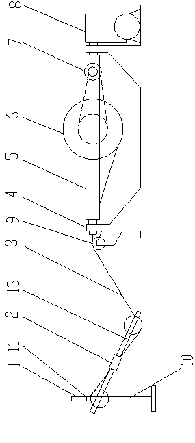
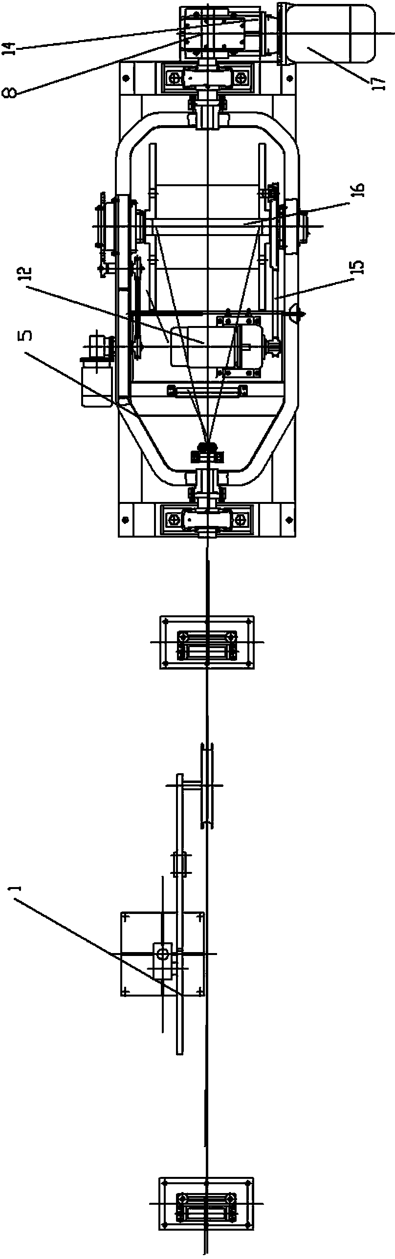
[0031] Such as figure 1 with 2 As shown, an optical fiber composite cable optical unit of the present invention is a cable pay-off device. The pay-off device includes a swing arm type tension dance wheel assembly 1, a tension adjustment slider 2, a pay-off stand base 4, a cradle stand 5, and The wire motor and drive assembly 7 and the cradle frame rotation drive assembly 8. The two shaft ends of the cradle frame 5 are movably fixed on the pay-off frame base 4, and the shaft end of the cradle frame 5 is rotated by the cradle frame fixed on the pay-off frame base 4 The drive assembly 8 drives and rotates. The pay-off motor and drive assembly 7 installed on th...


PUM


Abstract

The invention discloses an optical fiber composite cable optical unit cabling pay-off device. The optical fiber composite cable optical unit cabling pay-off device comprises a swing arm type tension dancing wheel assembly, a tension adjusting sliding block, a pay-off rack base, a bassinet stand, a pay-off motor, a driving assembly and a bassinet stand rotary driving assembly. The pay-off motor and the driving assembly installed on the bassinet stand drive an optical unit reel to rotate. A pay-off pulley is arranged on the pay-off rack base. After passing through the pay-off pulley, a cable unreeled from the optical unit reel passes through the swing arm type tension dancing wheel assembly. The invention further discloses an optical fiber composite cable optical unit and conductive cable core cabling method. The method comprises the steps of optical unit pay-off preparation, conductor cable core pay-off preparation and the like. The pay-off device has constant tension and the cable can be unreeled automatically, so that tension of an optical unit is kept stable, the optical unit and a conductive cable core are twisted, synchronous back-twist is achieved, and the optical transmission performance and the service life of the optical fiber composite cable are guaranteed.

Description

Technical field [0001] The invention relates to an optical fiber composite cable light unit forming and paying off device. [0002] The invention also relates to a method for forming a cable between the optical unit of the optical fiber composite cable and the conductive core. Background technique [0003] Because the allowable pay-off tension of the optical unit is small, especially the excess length of the optical fiber in the optical unit is small, fluctuations in the pay-off tension will cause the optical fiber to be unevenly stressed in the cable after the optical fiber is twisted with the conductive core of the cable. It may cause the optical fiber to break during construction and laying, and the optical fiber transmission performance will decrease during operation, which will seriously affect the service life of the product. [0004] There are two main types of cable forming equipment for power cables, one is the cradle type cable forming machine, and the other is the twisted...

Claims


Application Information

Patent Timeline
Patent Type & Authority Applications(China)
IPC IPC(8): B65H59/10B65H49/34
Inventor 王绍刚徐雪平
Owner 江苏通光强能输电线科技有限公司
Why Eureka
Try Eureka