
Loop-pile cutting circular machine

A circular knitting machine and large plate technology, which is applied to the weft knitting circular knitting machine with individual moving needles, textiles and papermaking, weft knitting, etc., can solve the problems of expensive blankets, insufficient wool surface density, and uneven surface. Achieve the effect of eliminating shearing, high density of wool surface and high weight

Active Publication Date: 2014-07-23
LIANYUNGANG YUANFENG MACHINERY
View PDF8 Cites 10 Cited by
  • Summary
  • Abstract
  • Description
  • Claims
  • Application Information

AI Technical Summary

Problems solved by technology

The structure of the existing loop cutting machine adopts the structure of the needle on the top and the knife on the bottom. Therefore, there are hooks at the hair end after the circle is cut, and the knife and needle are easily misplaced when the knife and needle are separated. The density of the hair surface is insufficient and the surface is not smooth. problems, making it impossible to weave high-quality products such as blankets, carpets, tapestries, etc.
However, although existing blanket weaving machines and fine knitting machines can weave blankets, the woven blankets are prone to shedding, the base fabric is stiff after gluing, and the woven blankets are expensive.

Method used

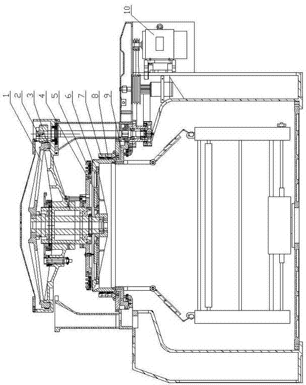
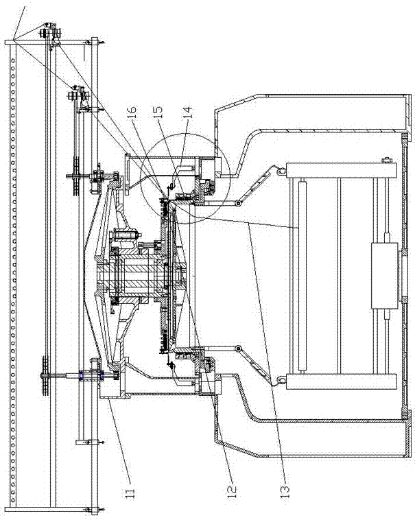
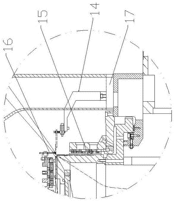

Image

  • Loop-pile cutting circular machine
  • Loop-pile cutting circular machine
  • Loop-pile cutting circular machine

Examples


Embodiment Construction

[0029] The specific technical solutions of the present invention will be further described below with reference to the accompanying drawings, so that those skilled in the art can further understand the present invention, without limiting their rights.

[0030] Refer to attached figure 1 , figure 2 and image 3 , a kind of ring-cutting velvet circular machine, comprising a support, a large plate and a large tripod 11, the large plate 17 is fixed on the top of the support, the large tripod 11 is fixed on the large plate 17 by supporting legs, the large plate 17 is equipped with a large plate gear 9, and A needle cylinder 8 coaxially arranged with the disk gear 9 is fixed on the large disk gear 9, and a lower disk saddle 7 is sleeved on the outside of the needle cylinder 8, and the lower end of the lower disk saddle 7 is fixedly connected to the large disk 17 through a saddle washer . The big tripod 11 is equipped with a big tripod gear 1 that rotates synchronously with the b...


PUM


Abstract

The invention provides a loop-pile cutting circular machine. A needle barrel is fixed on a large disc gear and sleeved by a lower disc saddle, a plurality of vertically-arranged needle triangles are arranged on the inner side of the lower disc saddle in the peripheral direction, and needle slots of the needle triangles of adjacent paths are connected to form knitting needle running tracks. A large tripod gear synchronously rotating with the large disc gear is installed on a large tripod, a knife disc tray is fixedly connected onto a lower shaft head of a gun barrel connected with the large tripod gear, a knife disc is arranged on the knife disc tray, a knife and hook assembly is installed on the knife disc, a knife disc saddle is arranged above the knife disc, and a knife and hook assembly triangle is arranged on the knife disc saddle. Fabrics woven by the loop-pile cutting circular machine are smooth in surface, free of hooked ends, high in hair side density, not prone to hair slip and soft in backing fabric, shearing, breaking and other after treatment steps can be omitted, and the production cost is greatly saved. The knife and hook assembly triangle adopts an arrangement mode that four paths form a group and is large in gap, not prone to shifting and good and stable in operation compared with arrangement modes of common machines.

Description

technical field [0001] The invention relates to a loop-cutting circular pile machine, in particular to a loop-cutting circular pile machine with needle-knife positions reversed. Background technique [0002] The loop cutting machine is used for napping and shearing while weaving. The woven fabric has a certain length of hair and is soft and comfortable. The main types of fabrics that can be produced are: coral velvet, carded velvet, sunflower velvet, plush, pine needle velvet, peacock velvet, straw velvet and various clothing fabrics. The structure of the existing loop cutting machine adopts the structure of the needle on the top and the knife on the bottom. Therefore, there are hooks at the hair end after the circle is cut, and the knife and needle are easily misplaced when the knife and needle are separated. The density of the hair surface is insufficient and the surface is not smooth. problems, making it impossible to weave high-quality products such as blankets, carpet...

Claims


Application Information

Patent Timeline
Patent Type & Authority Applications(China)
IPC IPC(8): D04B9/00D04B15/60D04B15/66
Inventor 侯永进徐睿晗唐凡枚吉安岩周洪勤
Owner LIANYUNGANG YUANFENG MACHINERY
Learn More