Silo top slip-form lifting construction method adopting spatial horizontal supporting system

A technology of horizontal support and construction method, which is applied in the direction of formwork/formwork/work frame, preparation of building components on site, building type, etc., which can solve the problems of insufficient bearing capacity of steel pipe truss structure and inability to get rid of it, so as to shorten the construction period , cost saving, clear force transmission effect

Inactive Publication Date: 2014-07-23
TIANJIN UNIV +1
View PDF4 Cites 5 Cited by
  • Summary
  • Abstract
  • Description
  • Claims
  • Application Information

AI Technical Summary

Problems solved by technology

On the basis of this support system, a steel center frame radial support platform appeared. This structure is a combination structure of fastener type steel pipe truss and steel truss beam. The steel pipe truss is restrained by using the steel truss beam as a horizontal rigid reinforcement Strengthening to prevent and control the problem of insufficient bearing capacity of the steel pipe truss structure caused by excessive deformation due to excessive load during use. These two methods are convenient in construction, safe and reliable, high in work efficiency and low in cost, but they still cannot get rid of the support from the bottom of the silo link

Method used


Image

  • Silo top slip-form lifting construction method adopting spatial horizontal supporting system
  • Silo top slip-form lifting construction method adopting spatial horizontal supporting system
  • Silo top slip-form lifting construction method adopting spatial horizontal supporting system

Examples


Embodiment Construction

[0024] The present invention will be described below in conjunction with the accompanying drawings and embodiments.

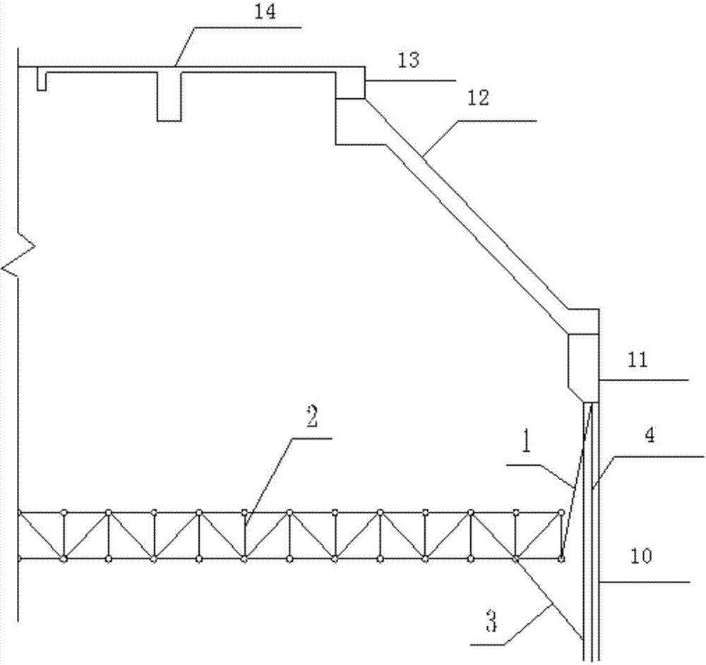
[0025] In order to clearly illustrate the construction method of the present invention, at first refer to Figure 1-3 Explain the spatial horizontal support system built during the construction process.

[0026] After the silo roof is constructed, it includes a large ring beam 11, an inclined cone shell 12, a small ring beam 13 and a platform beam plate 14. The silo roof steel pipe truss support system adopted in the present invention mainly includes multiple Steel wire rope 1, steel pipe truss 2, and lower support 3 several parts.

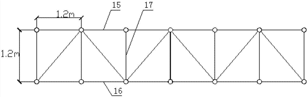
[0027] Steel pipe truss 2 is a space bar system formed by ordinary building scaffolding steel pipes and fasteners. It is an orthogonal space truss structure composed of a series of plane trusses, and its form is circular. The lengths of the upper chord 15 and the lower chord 16 of the steel pipe truss 2 are both 1.2m, and the hei...


PUM


Abstract

The invention belongs to the technical field of building structure engineering, and relates to the silo top slip-form lifting construction method adopting a spatial horizontal supporting system. The method includes the steps that a steel tube truss (2) is erected; a slip-form lifting system is prepared, wherein the height of a formwork (6) is the same as the length of chord members and the length of vertical rods, and the chord members and the vertical rods are adopted in the steel tube truss; the ends of upper chords of the steel tube truss (2) are fixed to an upper surrounding ring (71) of the slip-form lifting system, and the ends of lower chords of the steel tube truss (2) are fixed to a lower surrounding ring (72); slip-form construction is started above a silo funnel, and the steel tube truss (2) is supported to a construction position of a silo top construction layer; the upper portion of the steel tube truss (2) is dragged obliquely to a silo through a ring of steel wire rope (1), and the lower portion of the steel tube truss (2) is supported by the silo through a ring of lower supports (3); a climbing rod (8) is left in the silo wall (10), and the slip-form lifting system is demounted; silo top construction is conducted to demount the steel tube truss supporting system. The method has the advantages that construction is quick, the construction period can be obviously shortened, and components can be reused.

Description

Technical field [0001] The invention belongs to the technical field of building structure engineering and relates to a construction method for a silo roof. Background technique [0002] With the continuous increase of coal demand and the improvement of environmental protection requirements, a new type of coal bunker with large reserves, small footprint and in line with the requirements of sustainable development strategy has been widely used in coal preparation plants and coal storage systems of coal mines. In the construction of coal bunker engineering, the construction of the bunker roof structure is a key link in the construction process, and the design and checking calculation of the bunker roof structure support system are particularly important for the bunker roof construction. The construction method of the traditional support system is to erect the full hall frame, but with the progress of construction technology, the full hall frame formwork system is gradually repl...

Claims


Application Information

Patent Timeline
IPC IPC(8): E04H7/26E04G11/22
Inventor 赵海龙王铁成李勤山汪源王文星
Owner TIANJIN UNIV
Why Eureka
Try Eureka