Columnar hydraulic tappet

一种液压挺柱、柱状的技术,应用在柱状式液压挺柱领域,能够解决应力疲劳、应力集中等问题,达到增加疲劳强度、加工容易、产品重量增加的效果

Active Publication Date: 2014-07-23
HANGZHOU XZB TECH
View PDF6 Cites 20 Cited by
  • Summary
  • Abstract
  • Description
  • Claims
  • Application Information

AI Technical Summary

Problems solved by technology

[0008] However, the applicant found through research that the force of the plunger is not uniform on all parts, especially the head and neck are the key areas of force, which is the hidden danger of stress fatigue. The overall strength of the plunger is improved, but the technical problem of stress concentration is not solved

Method used


Image

  • Columnar hydraulic tappet
  • Columnar hydraulic tappet
  • Columnar hydraulic tappet

Examples


Embodiment 1

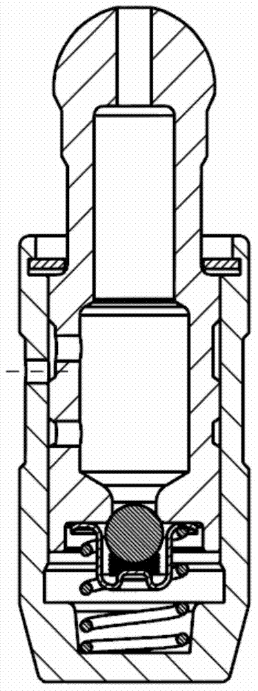
[0056] like Figure 4 Shown is a hydraulic tappet for a valve train of an internal combustion engine, the hydraulic tappet has a cylindrical housing (2), and an axially slidable plunger (1) is assembled inside the housing. On the lower face of the plunger (1) and the lower side of the housing (2) there is a high-pressure chamber (10) for hydraulic medium, which can be controlled by a check valve (3) located at the lower end of the plunger (1). closed. There is an outer ring groove (13) on the outer diameter of the shell (2) for the circulation of the hydraulic medium, and an inner ring groove (8) for the circulation of the hydraulic medium on the radial inner side of the shell. One or more oil holes (7) for connection.

[0057] The outer diameter of the plunger has a concave wide ring groove (5), and there are one or more oil holes (6) on the concave wide ring groove (5), and the inner ring groove (8) of the housing and the plunger The inner concave wide ring grooves (5) co...

Embodiment 2

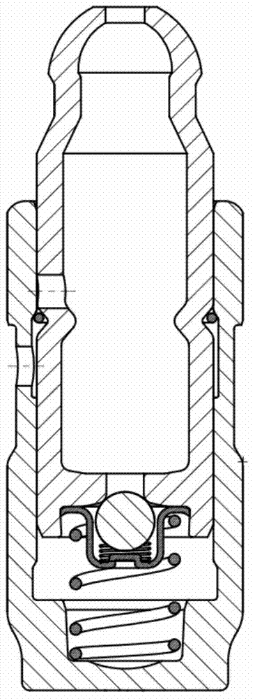
[0064] The difference from Example 1 is that, if Figure 5 As shown, there is a smooth neck (4B) between the head (11) and the stem of the plunger.

Embodiment 3

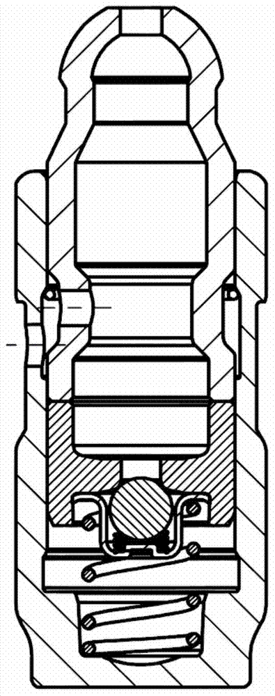
[0066] The difference from Example 1 is that, if Image 6 As shown, the positioning surface (15) of the plunger is a combination of a conical surface and an arc surface, the radius r of the arc portion is 0.3-0.8mm, and the cone angle α of the conical surface portion is 5°-15°.


PUM


Abstract

The invention relates to a columnar hydraulic tappet which comprises a shell. A plunger is correspondingly installed in the shell. A high-pressure cavity for a hydraulic medium extends between a sealing base of the plunger and the lower side of the shell and can be sealed through a check valve which is opened towards the high-pressure cavity. An outer ring groove for hydraulic medium circulation is formed in the outer diameter of the shell, an inner ring groove for hydraulic medium circulation is formed in the radial inner side of the shell, and one or more shell oil holes are formed between the inner ring groove and the outer ring groove. The plunger is composed of a sealed hemispherical head portion, a rod portion and a body portion. The columnar hydraulic tappet is characterized in that an inward-concave neck portion is arranged between the head portion of the plunger and the rod portion of the plunger, and the wall thickness of the neck portion is 105% to 120% the wall thickness of the rest of the plunger. The columnar hydraulic tappet is simple and firm in structure, the design that the wall thickness of the low-strengthen area of the single-body thin-walled hollow plunger is increased is adopted, and therefore both the requirement for increasing the oil storage amount in the plunger and the requirement for improving fatigue strengthen are considered.

Description

technical field [0001] The invention relates to a columnar hydraulic tappet. Background technique [0002] The hydraulic tappet has the function of automatically compensating the valve clearance, which reduces the impact and noise of the valve mechanism, reduces the wear of each working surface of the valve mechanism, and improves the engine's emission and combustion efficiency. [0003] The existing hydraulic tappet structure currently discloses the structure of several styles: [0004] like figure 1 As shown, the Chinese patent document CN201593451U discloses a hydraulic support element. The plunger of this structure is machined after cold heading, and the processing technology is complicated, time-consuming and laborious. The wall thickness of the streamline and the neck is thinner than other positions, and the two cross-sectional dimensions change suddenly, resulting in stress concentration, which has a great impact on the overall strength of the plunger. [0005] li...

Claims


Application Information

Patent Timeline
Patent Type & Authority Applications(China)
IPC IPC(8): F01L1/14F01L9/10
CPCF01L1/24F01L1/2405F01L2820/01F01L2303/00F01L9/10F01L1/146F15B1/26F15B15/1428F15B15/1447
Inventor 徐纳
Owner HANGZHOU XZB TECH
Why Eureka
Try Eureka