Eureka AIR delivers breakthrough ideas for toughest innovation challenges, trusted by R&D personnel around the world.

Vertical shaft giant energy wind turbine generator and floating giant energy wind turbine generator at sea

A technology of wind power generators and giant energy, which is applied in the direction of machines/engines, wind engines, renewable energy power generation, etc., and can solve the problems of complex overall structure of the control system, separation and dispersion of structure and control methods, multiple control points, etc.

Inactive Publication Date: 2014-07-23
陈晓通
View PDF2 Cites 3 Cited by
  • Summary
  • Abstract
  • Description
  • Claims
  • Application Information

AI Technical Summary

Problems solved by technology

[0007] However, in the innovative technical scheme of the unit mentioned above, for the structure of driving and adjusting the arrangement of blades of the wind wheel, a push-pull control structure driven and controlled by a micro-motor is set at the appropriate position on the rotating wind plate to realize the windward inverter plate on the rotating wind plate. The control structure and control method of the opening and closing form operation in the windward position, but the structure and the control method are separated and dispersed, and the control points are multiple, resulting in a complex overall structure of the control system

Method used


Image

  • Vertical shaft giant energy wind turbine generator and floating giant energy wind turbine generator at sea
  • Vertical shaft giant energy wind turbine generator and floating giant energy wind turbine generator at sea
  • Vertical shaft giant energy wind turbine generator and floating giant energy wind turbine generator at sea

Examples


Embodiment Construction

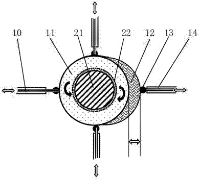
[0037] The operating mode of the new control structure and transmission structure of the vertical axis giant energy wind turbine generator set and the offshore floating giant energy wind turbine generator set of the present invention is illustrated by comparison with the diagrams:

[0038] Fan operation starts: the wind vane automatically controls the gear plate 22 that drives the directional plate to rotate to realize the rotation of the directional plate 19 to face the wind, so that the center line of the protruding structure of the movable convex plate 12 is always perpendicular to the wind direction to complete the wind control that adapts to the change of the wind direction;

[0039] Driven by a motor or hydraulic pressure, the movable convex plate 12 moves out of the fixed disc 11 and reaches the maximum moving distance, so as to achieve the maximum expansion and closure of the vertical wind wheel array blades 2 on the windward side, forming the maximum wind output state ...


PUM


Abstract

An orientation disc regulation and control system structure is adopted for a vertical shaft giant energy wind turbine generator. The drive structure is that the lower portion of a wind wheel shaft extends to the ground and is matched with a multi-generator regulation and control system, the top of a fan tower is located in the middle of a vertical wind wheel, and the effect that a fixing disc in the orientation disc regulation and control system structure is held through a tower top platform at the top of the tower is achieved. The vertical shaft giant energy wind turbine generator and a floating foundation are matched in an integrated mode to form a floating giant energy wind turbine generator at sea, and the large-scale application structural form is that multiple floating giant energy wind turbine generators form an integrated overall floating foundation structure through different arrangements and combinations.

Description

technical field [0001] The invention relates to a vertical axis giant energy wind turbine and an offshore floating giant wind turbine. By optimizing the wind wheel control structure and transmission structure, the structure and performance of the whole machine can be made more simple, efficient, economical and beautiful. Background technique [0002] The basis for the high-quality and large-scale development of the wind power industry is the expansion of the large-scale capacity of wind turbines. This is a global technical problem. The current large-scale wind turbines are formed by gradually enlarging the diameter specifications of the wind rotors in the form of small wind turbines. As a result, the formation and development of the theory of calculating the output capacity of wind rotors based on the "sweeping area" design has been triggered, resulting in the existence of two different output expansions of the "sweeping area" and "wind riding area" of the wind rotor blades o...

Claims


Application Information

Patent Timeline
Patent Type & Authority Applications(China)
IPC IPC(8): F03D3/00
CPCY02E10/74
Inventor 陈晓通
Owner 陈晓通
Why Eureka
Eureka Blog
Learn More