Eureka AIR delivers breakthrough ideas for toughest innovation challenges, trusted by R&D personnel around the world.

A Design Method of Tray Structure for Eliminating Gas Phase Drift Flow

A technology of structural design and tray, applied in the field of chemical vapor-liquid mass transfer separation equipment, can solve the problems of pouring at the entrance of tray, reduction of tray efficiency, liquid flooding, etc.

Active Publication Date: 2020-10-23
CHANGZHOU UNIV
View PDF6 Cites 0 Cited by
  • Summary
  • Abstract
  • Description
  • Claims
  • Application Information

AI Technical Summary

Problems solved by technology

Once the gas phase drift occurs, a large amount of gas phase flows out from the outlet of the tray, causing a large amount of mist entrainment; secondly, there is no or only a small amount of gas phase passing through the inlet of the tray, resulting in leakage at the inlet of the tray
This abnormal hydraulic phenomenon will not only significantly reduce the tray efficiency, but even induce tray flooding, affecting the normal operation of the column.
At present, some technologies such as multi-overflow trays, multi-downcomer trays and guided tray technologies can control the gas phase drift, but these technologies still have shortcomings: multi-overflow tray technology has complex design, especially with the increase of overflow number. There are disadvantages such as increase and long installation time; the efficiency of multi-downcomer trays is low; the technology of guided trays cannot cope with the conditions of high liquid / vapor ratio or lower limit operation of the distillation column

Method used


Image

  • A Design Method of Tray Structure for Eliminating Gas Phase Drift Flow
  • A Design Method of Tray Structure for Eliminating Gas Phase Drift Flow
  • A Design Method of Tray Structure for Eliminating Gas Phase Drift Flow

Examples


Embodiment 1

[0111] The design gas phase mass flow rate is 15000kg / hr, and the gas phase density is 2.5kg / m 3 , the mass flow rate of the liquid phase is 40000kg / hr, and the density of the liquid phase is 880kg / m 3 , the surface tension is 10N / m, and the viscosity is 1mPa·s. The mass transfer tray type is selected as a sieve tray column. Through the preliminary design, the structural parameters of the tray type are shown in Table 1:

[0112] Table 1 Design parameters of mass transfer tray structure

[0113]

[0114] The parameters calculated by formulas (1) to (9) are shown in Table 2:

[0115]Table 2 Calculation results of parameters related to liquid level gradient in mass transfer trays

[0116]

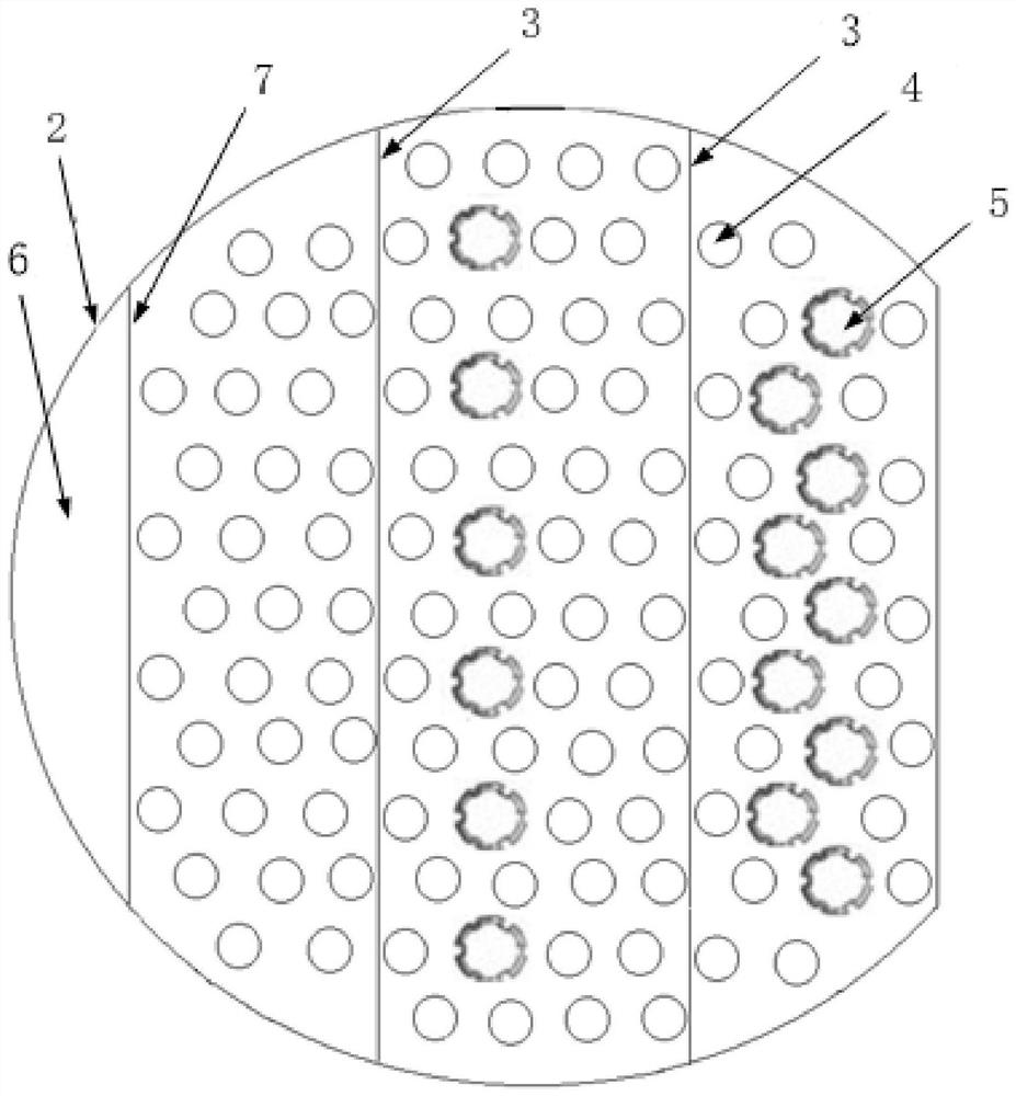
[0117] Divide the gas phase distribution plate into five zones, the length of each zone is 200mm, and take the gas phase distribution plate aperture ratio ratio coefficient of 1.4 (the gas phase distribution plate aperture ratio is 17.85%), then the vapor obtained by formula (15) is c...

Embodiment 2

[0124] The designed gas mass flow rate is 60000kg / hr and the gas phase density is 2.5kg / m 3 , the liquid mass flow rate is 70000kg / hr, and the liquid phase density is 880kg / m 3 , the surface tension is 10N / m, and the viscosity is 1mPa·s. The type of mass transfer tray is selected as sieve tray. Through preliminary design, the structural parameters of this tray are shown in Table 5:

[0125] Table 5 Design parameters of mass transfer tray structure

[0126]

[0127] The parameters calculated by formulas (1) to (9) are shown in Table 6:

[0128] Table 6 Calculation results of parameters related to liquid level gradient of mass transfer tray

[0129]

[0130] Divide the gas phase distribution plate into four zones, the length of each zone is 400mm, and take the gas phase distribution plate aperture ratio ratio coefficient of 1.4 (the gas phase distribution plate aperture ratio is 20.31%), then the gas phase calculated by formula (15) is obtained. The apparent hole veloc...

Embodiment 3

[0137] The designed gas mass flow rate is 60000kg / hr and the gas phase density is 2.5kg / m 3 , the liquid mass flow rate is 70000kg / hr, and the liquid phase density is 880kg / m 3 , the surface tension is 10N / m, and the viscosity is 1mPa·s. The type of mass transfer tray is selected as sieve tray. Through preliminary design, the structural parameters of this tray are shown in Table 9:

[0138] Table 9 Design parameters of mass transfer tray structure

[0139]

[0140] The parameters calculated by formulas (1) to (9) are shown in Table 10:

[0141] Table 10 Calculation results of parameters related to liquid level gradient in mass transfer trays

[0142]

[0143] Divide the gas distribution plate into 2 areas, the length of each area is 800mm, and take the gas phase distribution plate aperture ratio ratio coefficient of 1.4 (the gas phase distribution plate aperture ratio is 20.31%), then the gas phase calculated by formula (15) is obtained. The apparent hole velocity of...


PUM


Abstract

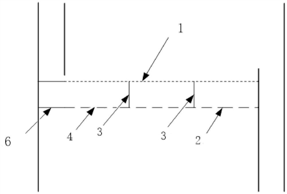
The invention discloses a column plate structure capable of eliminating gas-phase deflected flow and a design method. The structure includes a mass transfer column plate, wherein a gas phase distribution plate is added to below the mass transfer column plate, thus forming a double-layer column plate structure. The distance from the gas phase distribution plate to the mass transfer column plate is20-300 mm. The gas phase distribution plate includes a non-holed zone, at one side, and a holed zone being the area except the non-holed zone. Horizontal baffles are formed on the holed zone of the gas phase distribution plate to separate the space, formed by the gas phase distribution plate and the mass transfer column plate, into several zones, wherein valve holes, in different numbers, are formed uniformly in each zones on the gas phase distribution plate, but the ratio of pore area of each zone to the area of each zone is equal. A part of the valve holes are provided with float valves. Thecolumn plate structure is simple and can effectively eliminate the forming condition of the gas-phase deflected flow and make gas-phase flow uniform. The structure greatly improves operating flexibility and separation efficiency.

Description

technical field [0001] The invention relates to a tray structure and a design method for eliminating gas phase bias flow, and belongs to the technical field of chemical vapor-liquid mass transfer and separation equipment. Background technique [0002] At present, despite the emergence of a variety of new separation technologies, distillation is still the most widely used separation technology in industry. Among them, the most widely used rectification operation mode is the tray column. When the liquid phase flows on the tray, due to the influence of frictional resistance, the liquid layer on the tray will form a liquid level drop, resulting in uneven distribution of the liquid phase on the tray, and then forming a gas phase bias flow on the tray, especially in large tray towers . Once the gas phase deviation occurs, a large amount of gas phase flows out from the tray outlet, causing a large amount of mist entrainment; secondly, no or only a small amount of gas phase passes...

Claims


Application Information

Patent Timeline
Patent Type & Authority Patents(China)
IPC IPC(8): B01D3/14B01D3/32
CPCB01D3/14B01D3/324
Inventor 王俊周鑫韶晖冷一欣黄春香孙雪妮
Owner CHANGZHOU UNIV
Why Eureka
Eureka Blog
Learn More