
High-precision remote displacement sensor

A displacement sensor, high-precision technology, applied in the field of displacement sensor for remote measurement, can solve problems such as increasing system complexity, and achieve the effect of simple and reliable structure, high precision, and self-adaptive measurement distance

Active Publication Date: 2014-07-23
西安敏文测控科技有限公司
View PDF8 Cites 9 Cited by
  • Summary
  • Abstract
  • Description
  • Claims
  • Application Information

AI Technical Summary

Problems solved by technology

The main problem with this type of displacement sensor at present is that the CCD image sensor needs to be used in conjunction with a collimated laser, which increases the complexity of the system

Method used


Image

  • High-precision remote displacement sensor
  • High-precision remote displacement sensor
  • High-precision remote displacement sensor

Examples


Embodiment Construction

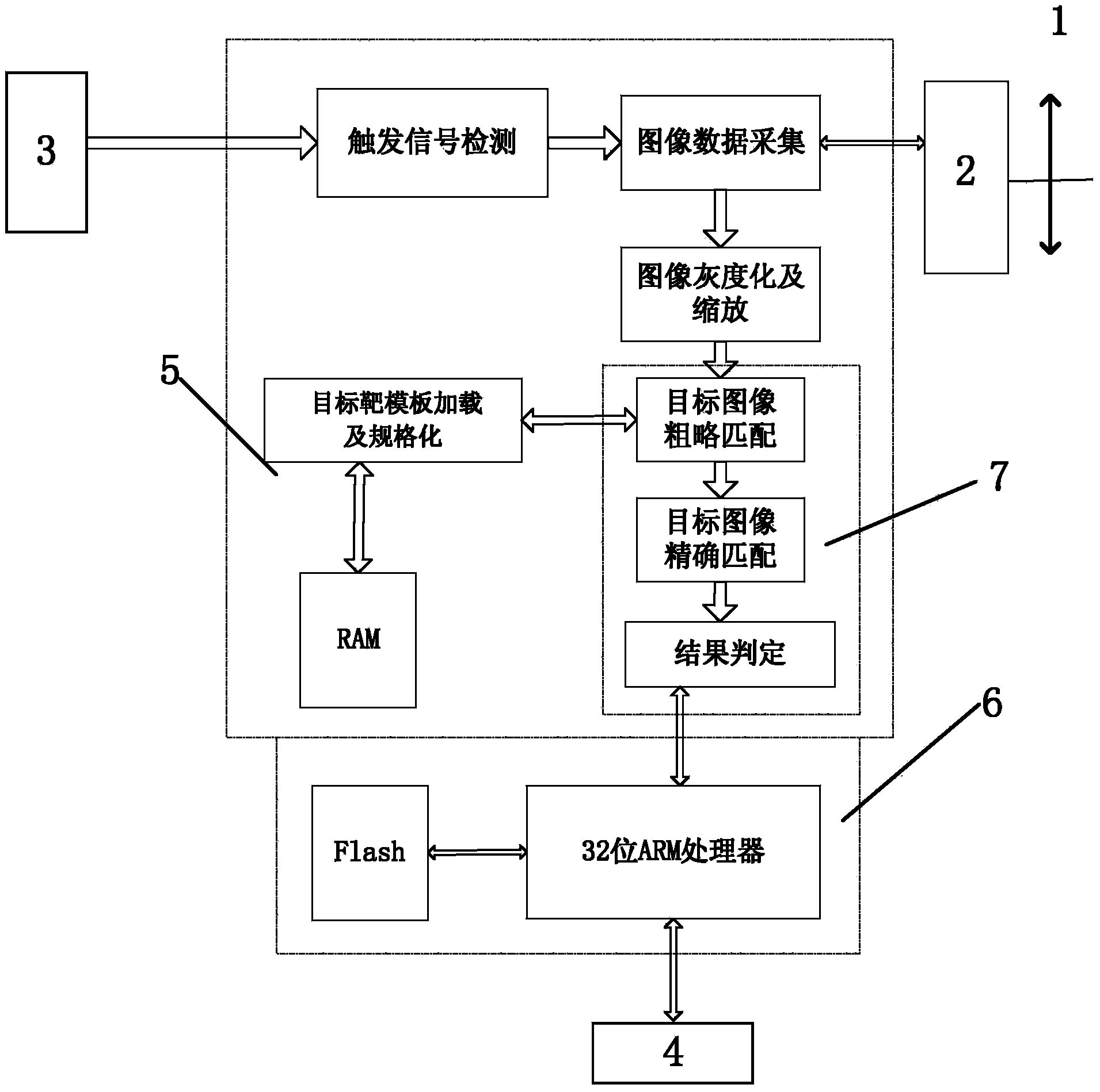
[0037] Such as figure 1 As shown, the remote displacement sensor of the present invention includes an optical lens 1 , an image sensor 2 , a core control function unit 5 , a processing storage unit 6 , a trigger control unit 3 and a remote communication unit 4 .

[0038] The optical lens 1 is aimed at the target set on the target to be measured. In the application, a zoom lens can be selected to image targets of different distances and sizes onto the image sensor. This working method has good adaptability to the measurement target and is It has the characteristics of large measurement range, wherein the image sensor 2 is a CCD or CMOS sensor, which is used to acquire images of the measured target in real time.

[0039] The target of the present invention can be a specific pattern on the target object or a continuously working powered target. This device does not have high requirements on the target. If a powered LED or LD light strip is used as the target, it can work 24 hour...


PUM


Abstract

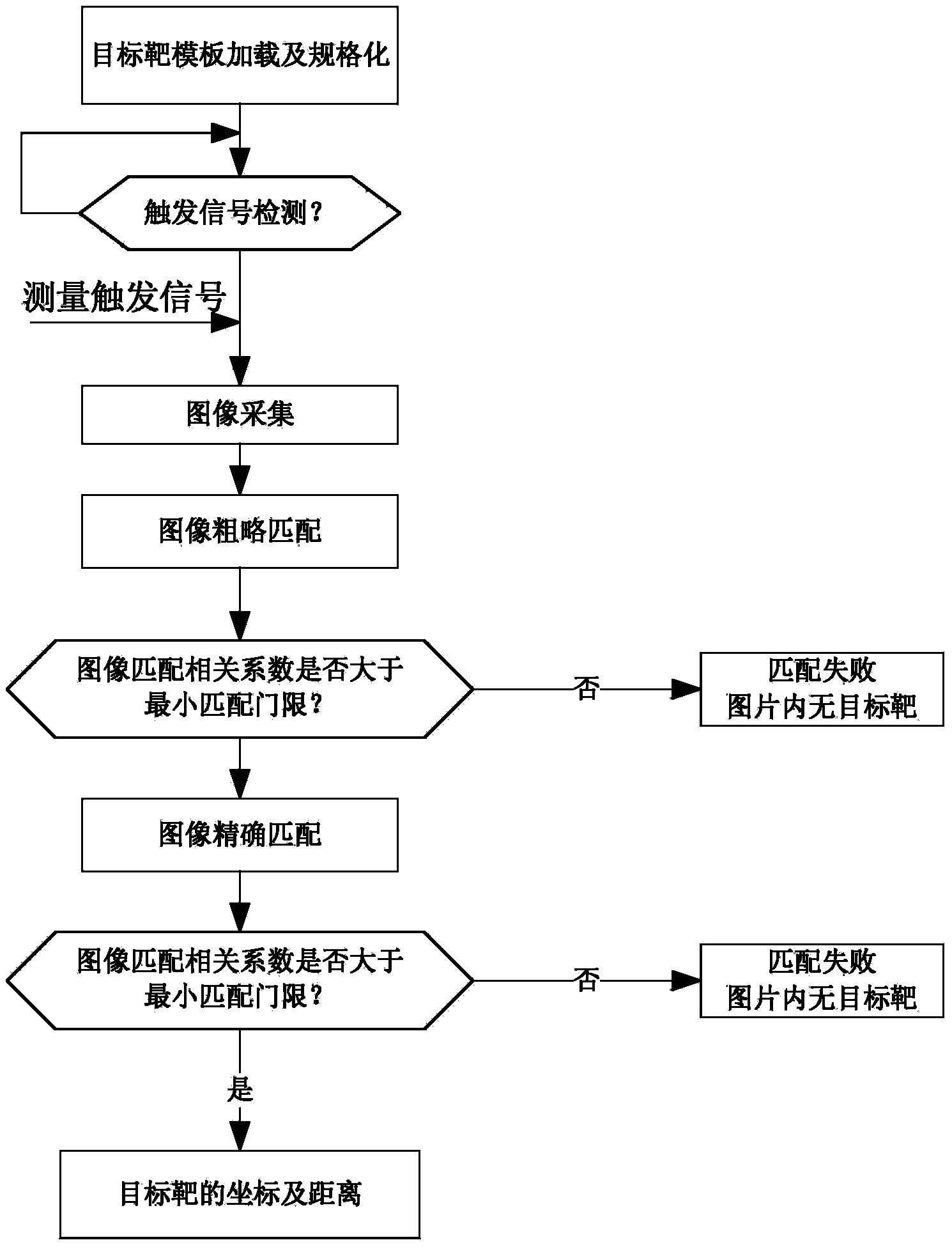
The invention discloses a high-precision remote displacement sensor which comprises an optical lens (1), an image sensor (2), a core control functional unit (5), a processing storing unit (6), a trigger control unit (3) and a remote communication unit (4). The core control functional unit (5) comprises a trigger signal detection module, a target template loading and standardizing module, an image data acquisition module, an image graying and zooming module and a target image matching detection module (7). According to the high-precision remote displacement sensor, the image sensor is used for obtaining images of a dart on a measured target, and displacement parameters of a bridge are obtained through image processing; the high-precision remote displacement sensor has the advantages of being high in precision, simple and reliable in structure, capable of conducting two-dimensional real-time measurement, large in measuring span and the like, thereby being suitable for long-term, online and multi-point measurement.

Description

technical field [0001] The invention belongs to the technical field of mechanical measurement, and relates to a displacement and deformation measuring device applicable to targets such as bridges, dams and structural parts, in particular to a displacement sensor for remote measurement. Background technique [0002] The deformation of bridges, dams, structural parts and other objects mainly includes static deformation and dynamic deformation. Static deformation refers to the deformation that changes slowly such as foundation subsidence, inclination and stress relaxation. Dynamic deformation refers to the deformation caused by wind, temperature, earthquake and traffic load. The short-term deformation caused by , its parameter monitoring plays an important role in the security assessment analysis of the target. Many countries in the world have invested a lot of manpower and material resources in the research of bridge deformation measurement technology. [0003] Traditional br...

Claims


Application Information

Patent Timeline
Patent Type & Authority Applications(China)
IPC IPC(8): G01B11/02G01B11/16
Inventor 高文武陈长军郭敏徐克强朱昌林
Owner 西安敏文测控科技有限公司
Learn More