Real-time bridge monitoring system

A real-time monitoring system and bridge technology, applied in the field of mechanical measurement, can solve the problems of waste of data resources, many types of sensors, insufficiency, etc., to reduce the pressure of data storage and backup, compact structure, simple and reliable, and improve measurement accuracy. Effect

Active Publication Date: 2014-07-23
郭敏 +1
View PDF7 Cites 34 Cited by
  • Summary
  • Abstract
  • Description
  • Claims
  • Application Information

AI Technical Summary

Problems solved by technology

The laser displacement meter can realize sub-millimeter displacement measurement, but the range can only reach tens of centimeters, which cannot meet the measurement of large deformation of bridges with a large span, and its vertical displacement can reach meter level; GPS positioning measurement method can realize real-time Online measurement of large deformation of bridges, but its accuracy can reach centimeter level, and the cost is high, which limits its popularization and application
[0004] In addition, there are still the following problems in the application: (1) There are many types of sensors, and it is difficult to achieve accurate synchronization of various output data, which brings difficulties to the fusion, processing and analysis of subsequent data; (2) The

Method used


Image

  • Real-time bridge monitoring system
  • Real-time bridge monitoring system
  • Real-time bridge monitoring system

Examples


Embodiment Construction

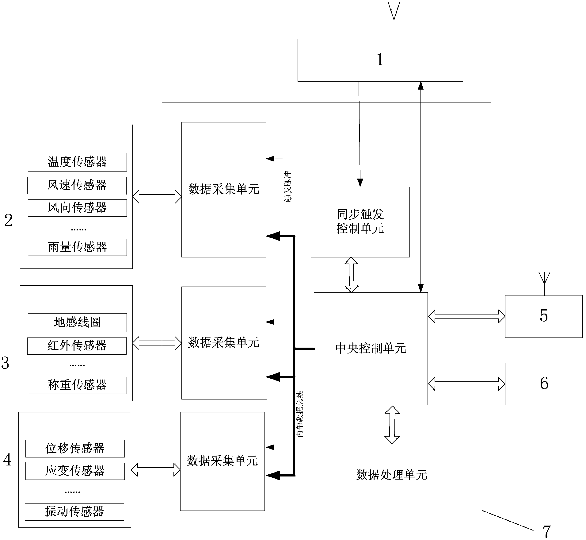
[0044] Such as figure 1 As shown, the bridge real-time monitoring system of the present invention includes a core control processing module 7 and an environment detection sensor unit 2 connected with the core control processing module 7, a flow detection sensor unit 3, a structure detection sensor unit 4, a capture camera 6, and GPS timing Unit 1 and wireless data transmission unit 5.

[0045] The environment detection sensor unit 2 includes one or more combinations of temperature sensors, wind speed sensors, and rainfall sensors; the flow detection sensor unit 3 includes one or more combinations of ground sensing sensors, infrared sensors, and load cells; the structure The detection sensor unit 4 includes one or a combination of displacement sensors, strain sensors, and vibration sensors.

[0046] The core control processing module 7 includes a central control unit and a data acquisition unit connected to the central control unit, a synchronous trigger control unit and a dat...


PUM


Abstract

The invention discloses a real-time bridge monitoring system which comprises a kernel control processing module (7), an environment detection sensor unit (2), a flow detection sensor unit (3), a structure detection sensor unit (4), a snapshot camera (6), a GPS time service unit (1) and a wireless data transmission unit (5). The environment detection sensor unit (2), the flow detection sensor unit (3), the structure detection sensor unit (4), the snapshot camera (6), the GPS time service unit (1) and the wireless data transmission unit (5) are connected with the kernel control processing module (7). According to the real-time bridge monitoring system, time signals of a GPS are introduced in a measuring result, time marking codes are additionally arranged for output data of sensors and output data of the camera, the accurate synchronization of the data is achieved, and a synchronization standard is provided for subsequent data processing and analyzing. Meanwhile, according to the analysis of the data of structure detection sensors and the judgment of threshold values, whether a target object has dynamic deformation is determined; the snapshot camera is triggered to work according to the threshold values of signals, the dynamic deformation is monitored completely, and a bridge is monitored comprehensively and reasonably; the real-time bridge monitoring system has the advantage of saving data resources and reducing the pressure of wireless data transmission and the pressure of data storage and backup.

Description

technical field [0001] The invention belongs to the technical field of mechanical measurement, and relates to a displacement and deformation measurement technology applicable to bridges, dams, structural parts and other targets, in particular to a real-time monitoring system for parameters and images of bridge deformation. Background technique [0002] The deformation of bridges, dams, structural parts and other objects mainly includes static deformation and dynamic deformation. Static deformation refers to the deformation that changes slowly such as foundation subsidence, inclination and stress relaxation. Dynamic deformation refers to the deformation caused by wind, temperature, earthquake and traffic load. The short-term deformation caused by , its parameter monitoring plays an important role in the security assessment analysis of the target. Many countries in the world have invested a lot of manpower and material resources in the research of bridge deformation measuremen...

Claims


Application Information

Patent Timeline
IPC IPC(8): G01B11/16
Inventor 曾有全高文武屈战辉杨利峰郭敏黄元库陈长军徐克强朱昌林
Owner 郭敏
Why Eureka
Try Eureka