Device and method for measuring flow field velocity that can eliminate vibration interference

A technology for flow velocity measurement and vibration elimination, which is applied in the directions of measuring devices, fluid velocity measurement, velocity/acceleration/shock measurement, etc. It can solve problems such as small application range, unusable internal flow field, and reduced signal-to-noise ratio of kerosene fluorescence images. Achieve good applicability and improve the effect of measurement signal-to-noise ratio

Active Publication Date: 2016-05-18
NORTHWEST INST OF NUCLEAR TECH
View PDF2 Cites 2 Cited by
  • Summary
  • Abstract
  • Description
  • Claims
  • Application Information

AI Technical Summary

Problems solved by technology

However, since the fluorescence of the marker molecule and the fluorescence of kerosene in the flow field do not overlap in spectrum, it is guaranteed that t 2 Molecular fluorescence image is clear at the same time, so that t 1 Moment kerosene fluorescence image signal to noise ratio is greatly reduced
Moreover, not all flow fields have kerosene molecules, and this method is less applicable
The prior art (JenniferA.Inman, Laser-Induced Fluorescence VelocityMeasurements in SupersonicUnderexpandedImpingingJets.AIAA2010-1438) aimed at the open flow field, designed a marking line that crosses the entire flow field for flow field measurement, so that the two ends of the marking line are in a static flow field, and the marking line The central part of the line is in the flowing flow field, and the positions of the marker molecules in the stationary flow field and the flowing flow field in an image are respectively taken as t 1 and t 2 The location of the moment also effectively reduces the vibration interference, but this method is only applicable to the open flow field, and cannot be used for the restricted internal flow field

Method used


Image

  • Device and method for measuring flow field velocity that can eliminate vibration interference
  • Device and method for measuring flow field velocity that can eliminate vibration interference
  • Device and method for measuring flow field velocity that can eliminate vibration interference

Examples


Embodiment

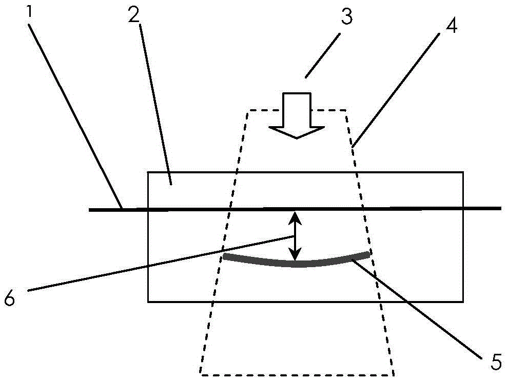
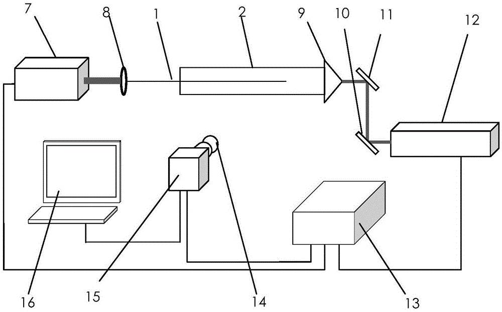
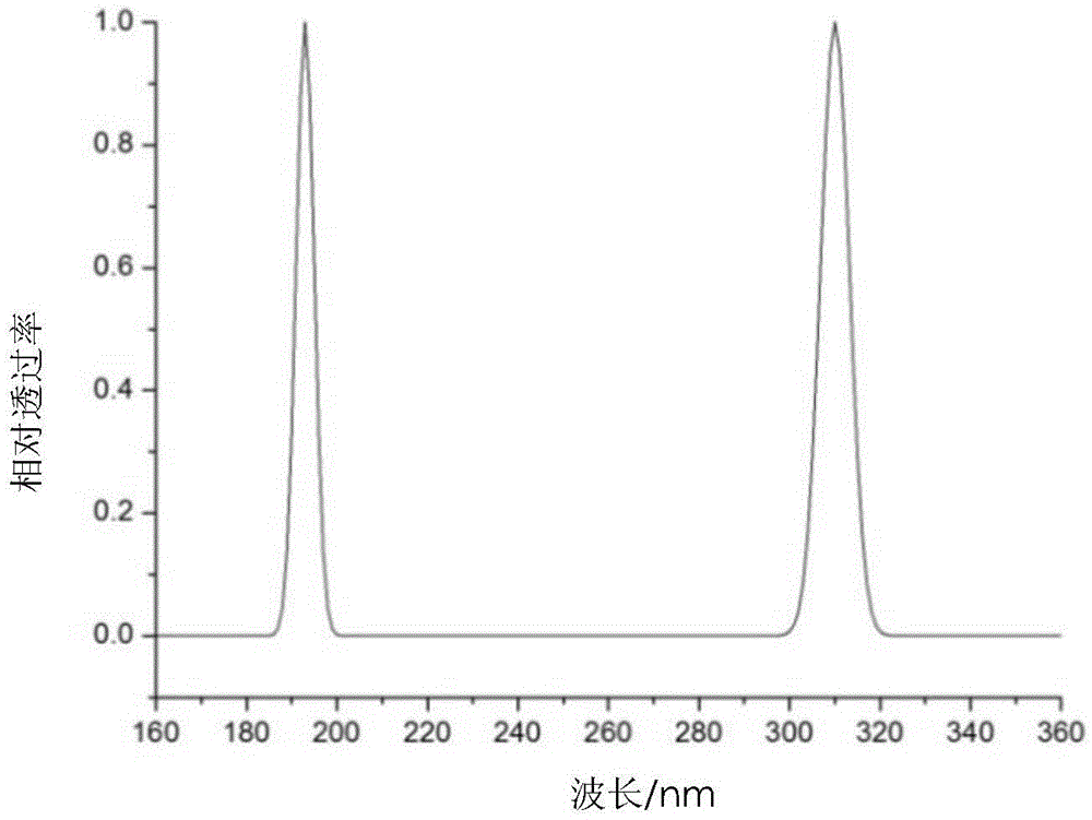
[0044] Single-line OH-marked velocity measurement (HTV) technique to avoid vibration interference. The marking laser 7 is an ArF excimer laser with an output wavelength of 193nm, a pulse energy of about 50mJ, and a pulse width of 20ns. It interacts with water in the flow field to generate OH as a flow field mark. It is shown that the laser system 8 is a frequency doubled YAG laser + tunable dye laser + frequency doubler system, the output laser wavelength is about 282nm, and the energy is about 5mJ. Through wavelength tuning, the display laser can be absorbed by OH resonance and generate fluorescence radiation with a wavelength of about 310nm. A filter is added in front of the gated ICCD camera for shooting OH fluorescence. The ICCD camera can be switched on and off twice in less than 2 μs, and the opening time of each gate is set to 50 ns. The time delay adjustment device is a digital pulse delay generator.

[0045] image 3 It is the filter parameter in the embodiment. Th...


PUM


Abstract

The invention discloses a flow field flow velocity measuring device and method capable of eliminating vibration interference. The flow field flow velocity measuring device comprises a marking laser, a display laser, an ICCD camera and a delay generator. Output laser of the marking laser is shaped to be linear light beams, output laser of the display laser is shaped to be piece-shaped light beams, the linear light beams of the marking laser are located in the plane where the piece-shaped light beams of the display laser are located, the piece-shaped light beams of the display laser are located in a flow field to be measured, the ICCD camera right faces the piece-shaped light beams for imaging, and three delay output ends of the delay generator are connected with the marking laser, the display laser and the ICCD camera respectively. In the flowing process of a flow field, Rayleigh scattering light signals of the marking laser are shot to be used as an image of one moment of a marking line, the influence of strong vibration on measuring precision in the molecular marking speed measuring technology can be effectively reduced, changes on the current common devices are not large, no special requirements for the flow field exist, and adaptability is good.

Description

technical field [0001] The invention belongs to the related technical field of flow field velocity measurement, in particular to a flow field flow velocity measurement device and method for avoiding vibration interference in molecular labeling velocity technology suitable for strong vibration environment. Background technique [0002] In the study of flow field characteristics, accurate velocity measurement is of great significance for understanding flow field structure, flow field dynamics analysis and numerical calculation model correction. The non-contact optical measurement technology has no interference to the flow field and has high temporal and spatial resolution. It is currently a commonly used method for measuring flow field velocity. Optical velocity measurement methods include laser Doppler velocimetry (laserDopplervelocimetry, LDV), particle imaging velocity measurement technology (particle imagevelocimetry, PIV), etc. [0003] Molecular tagging velocity measure...

Claims


Application Information

Patent Timeline
Patent Type & Authority Patents(China)
IPC IPC(8): G01P5/26
Inventor 叶景峰王晟邵珺张振荣李国华胡志云
Owner NORTHWEST INST OF NUCLEAR TECH
Why Eureka
Try Eureka