
Frequency Modulation Continuous Wave Radar System Based on Random Switching Array Antenna

A switch array antenna, frequency modulation continuous wave technology, applied in radio wave measurement system, radio wave reflection/re-radiation, re-radiation, etc., can solve the problems of long data acquisition time, inability to effectively solve space-time coupling, space-time coupling, etc. , to achieve the effect of increasing the unambiguous distance, reducing the cost and complexity, and reducing the requirements

Active Publication Date: 2016-07-27
TSINGHUA UNIV
View PDF5 Cites 0 Cited by
  • Summary
  • Abstract
  • Description
  • Claims
  • Application Information

AI Technical Summary

Problems solved by technology

However, the disadvantage of this method is that it takes a long time to obtain data, and it takes multiple signal transmission cycles to obtain enough data for the estimation of azimuth, distance, and speed.
But the disadvantage of this method is that the phase difference of signals received by adjacent array elements will not only be caused by the angle of the target, but also be caused by the switching time of the switch. This method will cause the problem of space-time coupling.
However, this technology is still limited to the way of sequential switching of switches, which cannot effectively solve the problem of space-time coupling.

Method used


Image

  • Frequency Modulation Continuous Wave Radar System Based on Random Switching Array Antenna
  • Frequency Modulation Continuous Wave Radar System Based on Random Switching Array Antenna
  • Frequency Modulation Continuous Wave Radar System Based on Random Switching Array Antenna

Examples


Embodiment Construction

[0035] Embodiments of the present invention are described in detail below, examples of which are shown in the drawings, wherein the same or similar reference numerals designate the same or similar elements or elements having the same or similar functions throughout. The embodiments described below by referring to the figures are exemplary only for explaining the present invention and should not be construed as limiting the present invention.

[0036] In describing the present invention, it should be understood that the terms "center", "longitudinal", "transverse", "upper", "lower", "front", "rear", "left", "right", " The orientations or positional relationships indicated by "vertical", "horizontal", "top", "bottom", "inner" and "outer" are based on the orientations or positional relationships shown in the drawings, and are only for the convenience of describing the present invention and Simplified descriptions, rather than indicating or implying that the device or element refe...


PUM


Abstract

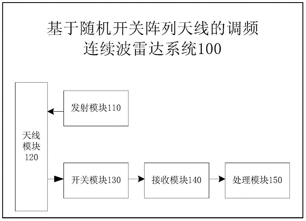
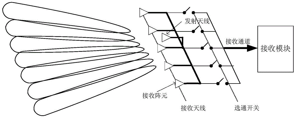
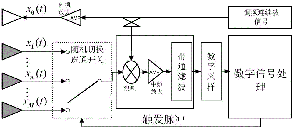
The invention provides a frequency modulated continuous wave radar system based on random switching array antennas. The frequency modulated continuous wave radar system comprises a transmitting module, an antenna module, a switching module, a receiving module and a processing module, wherein the antenna module comprises the transmitting antenna and the receiving antenna, the transmitting antenna transmits transmitting signals, so that targets are scanned, and the receiving antenna receives target reflecting signals; the switching module comprises multiple gating switches and controls multiple receiving array elements to be connected with a single receiving channel, and the gating switches are switched randomly, so that the target reflecting signal of the receiving array element connected with the gating switch which is currently connected occupies the receiving channel; synthesized signals in the receiving channel and the transmitting signals are mixed through the receiving module, intermediate-frequency amplification and band-pass filtering are conducted on the mixed signals, and therefore intermediate-frequency signals are obtained; digital sampling is conducted on the intermediate-frequency signals and following processing is conducted through the processing module. Cost and complexity of the radar system can be effectively reduced by the system and the problem of space-time coupling caused by sequential switching of the switches can be effectively solved.

Description

technical field [0001] The invention relates to the technical field of radar detection, in particular to a frequency modulation continuous wave radar system based on a random switch array antenna. Background technique [0002] Frequency modulated continuous wave radar has the characteristics of good environmental adaptability, high resolution, good system stability, etc., and can measure the distance and radial velocity of the target at the same time. For frequency modulated continuous wave radar, the azimuth information of the target can be obtained by using an array antenna. Array antenna radar has high precision, high resolution and high stability in azimuth measurement, so it is often used as a solution to achieve azimuth information acquisition. [0003] At present, there are mainly the following frequency modulation continuous wave radar technologies: [0004] 1. Detlefsen J, Troll T, Rozmann Mand Zeilinger W. System aspects and design of automotive collision warning...

Claims


Application Information

Patent Timeline
Patent Type & Authority Patents(China)
IPC IPC(8): G01S13/58
CPCG01S7/006G01S7/352G01S13/584
Inventor 孟华东胡晨曦张祎博刘一民王希勤
Owner TSINGHUA UNIV
Learn More