Manufacturing method for shading adhesive tape and backlight module of shading adhesive tape

A technology of a backlight module and a manufacturing method, which is applied in the directions of shading, optics, light source, etc., and can solve problems such as dark bands on the lugs, bright lines on the top of a narrow-frame display, and LED rays, so as to avoid dark bands on the lugs and eliminate bright lines on the top and the effect of the LED ray phenomenon

Inactive Publication Date: 2014-07-23
AU OPTRONICS CORP
View PDF0 Cites 7 Cited by
  • Summary
  • Abstract
  • Description
  • Claims
  • Application Information

AI Technical Summary

Problems solved by technology

However, B / W blackout tape will bring the problem of top bright line of narrow bezel display and LED ray problem
If B / B light-shielding tape is used, although it can effectively solve the above-mentioned problems of bright lines on the top and LED rays, the black rubber surface will cover the lugs of the optical diaphragm, resulting in obvious dark bands of lugs
As a result, in the prior art, no matter whether you use B / B light-shielding tape or B / W light-shielding tape, it has its own inherent shortcomings in the taste of narrow-frame displays.

Method used


Image

  • Manufacturing method for shading adhesive tape and backlight module of shading adhesive tape
  • Manufacturing method for shading adhesive tape and backlight module of shading adhesive tape
  • Manufacturing method for shading adhesive tape and backlight module of shading adhesive tape

Examples


Embodiment Construction

[0032] In order to make the technical content disclosed in this application more detailed and complete, reference may be made to the drawings and the following various specific embodiments of the present invention, and the same symbols in the drawings represent the same or similar components. However, those skilled in the art should understand that the examples provided below are not intended to limit the scope of the present invention. In addition, the drawings are only for schematic illustration and are not drawn according to their original scale.

[0033] The specific implementation manners of various aspects of the present invention will be further described in detail below with reference to the accompanying drawings.

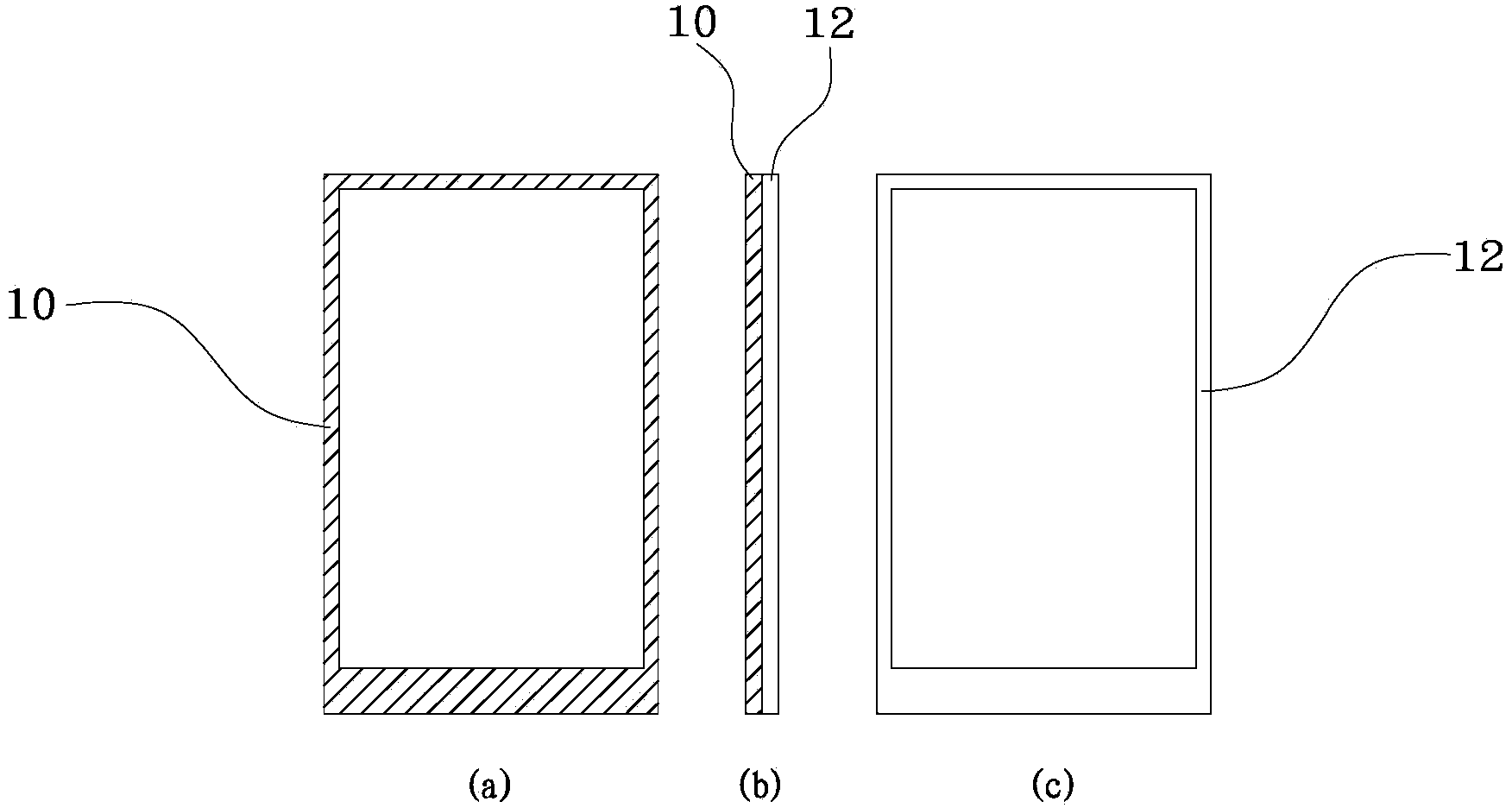
[0034] figure 1 (a)~ figure 1 (c) shows a schematic structural view of a light-shielding tape used in a backlight module of a narrow-frame display in the prior art.

[0035] refer to figure 1 (a)~ figure 1 (c), the existing light-shielding tape has a B...


PUM


Abstract

The invention provides a manufacturing method for shading adhesive tape used for a narrow-frame displayer and a backlight module of the shading adhesive tape. The backlight module comprises an LED backlight source, a light guide plate on the side edge of the LED backlight source and a multi-layer optical membrane above the light guide plate. The backlight module further comprises the annular shading adhesive tape, the shading adhesive tape comprises a first adhesive layer, a second adhesive layer and a third adhesive layer, the first adhesive layer is provided with a black adhesive face and located on the same side and the opposite side of the LED backlight source, the second adhesive layer is provided with a white adhesive face, overlapped with the first adhesive layer and located on a clamping lug part of the optical membrane, and the third adhesive layer is provided with a black adhesive face and arranged at the upper end and the lower end of the second adhesive layer. Compared with the prior art, the top bright line and the LED radial phenomena of the narrow-frame displayer are eliminated through the third adhesive layer with the black adhesive face, and an existing clamping lug dark band is avoided through the second adhesive layer with the white adhesive face.

Description

technical field [0001] The invention relates to a display with a narrow frame, in particular to a method for manufacturing a light-shielding adhesive tape used in the display with a narrow frame and a backlight module thereof. Background technique [0002] In recent years, a liquid crystal display device (Liquid Crystal Display, LCD) using a liquid crystal display panel as a display screen has been widely used in various applications due to its advantages of light weight and thin body. In a liquid crystal display panel, a glass substrate on which wiring and electrodes are formed is arranged in parallel to a counter substrate, and liquid crystal is sandwiched between the two substrates. Polarizing plates (for example, an upper polarizer and a lower polarizer) are respectively pasted on two sides of the liquid crystal display panel. The display area of ​​the liquid crystal display panel is composed of many pixels, and a signal corresponding to a display image is applied to ea...

Claims


Application Information

Patent Timeline
Patent Type & Authority Applications(China)
IPC IPC(8): G02F1/13357F21S8/00F21V1/00F21V1/26F21Y101/02
Inventor 林均祺杨青桑
Owner AU OPTRONICS CORP
Why Eureka
Try Eureka