Unmanned aerial vehicle ground sliding deviation rectification control device and method
A control device and unmanned aerial vehicle technology, applied in the field of aircraft control, can solve problems such as deviation correction performance degradation, system divergence, and difficulty in adapting deviation correction control
Inactive Publication Date: 2014-07-23
INST OF AUTOMATION CHINESE ACAD OF SCI
6 Cites 23 Cited by
AI-Extracted Technical Summary
Problems solved by technology
But the problem is that the speed changes during the autonomous take-off and landing process of t...
Abstract
The invention provides an unmanned aerial vehicle ground sliding deviation rectification control device and method. The device comprises a GPS module, a magnetic heading device, a deviation rectification controller, an inertial measurement unit, a steering engine servo controller and a front wheel steering engine. The longitude and latitude and ground velocity vector information of an unmanned aerial vehicle are acquired through the GPS module. The magnetic course information of the unmanned aerial vehicle is acquired through the magnetic heading device. The triaxial attitude angle, triaxial angular rate and body coordinate system velocity vector information of unmanned aerial vehicle motion are acquired through the inertial measurement unit. The deviation rectification controller carries out deviation rectification control calculation according to the parameters acquired by the GPS module, the magnetic heading device and the inertial measurement unit, and a steering engine control instruction is formed to be sent to the steering engine servo controller. The steering engine servo controller receives the steering engine control instruction sent by the deviation rectification controller, and power amplification signals are generated and used for driving the front wheel steering engine. Front wheel deflection is formed through the front wheel steering wheel according to the power amplification signals output by the steering engine servo controller, and therefore deviation rectification motion trajectory tracking on the unmanned aerial vehicle is caused.
Application Domain
Attitude controlAdaptive control
Technology Topic
Inertial measurement unitEngineering +7
Image
Examples
- Experimental program(1)
Example Embodiment
[0025] In order to make the object, technical solution and advantages of the present invention clearer, the present invention will be further described in detail below in conjunction with specific embodiments and with reference to the accompanying drawings.
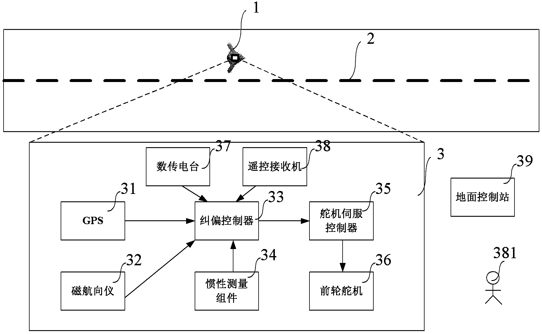
[0026] figure 1 It shows the structural diagram of the UAV sliding deviation correction control device in the present invention. like figure 1 As shown, the unmanned aerial vehicle sliding deviation correction control device includes a GPS module 31, a magnetic heading instrument 32, a deviation correction controller 33, an inertial measurement component 34, a steering gear servo controller 35, a front wheel steering gear 36, a digital transmission station 37, a remote control Receiver 38, ground control station 39. The UAV sliding deviation correction control device 3 is installed on the UAV 1, so that the UAV 1 always performs trajectory tracking along the runway centerline 2 during the autonomous take-off and landing ground taxiing process.
[0027] The deviation correction controller 33 is connected with the GPS module 31, the magnetic heading instrument 32, and the inertial measurement component 34, and is used to extract the sliding motion parameters of the UAV 1, and perform deviation correction control calculations according to these parameters, and form steering gear control commands to send To the steering gear servo controller 35. The steering gear servo controller 35 forms a power amplified signal to drive the front wheel steering gear 36 to perform sliding and deviation correction control.
[0028] The GPS module 31 provides the latitude and longitude and ground speed vector information of the UAV 1 movement.
[0029] The magnetic heading instrument 32 provides magnetic heading information of the movement of the UAV 1 .
[0030] The inertial measurement component 34 provides the three-axis attitude angle (roll, pitch, yaw angle) of the UAV 1 movement, the three-axis angular rate (roll, pitch, yaw rate), and the inertial navigation ground speed.
[0031] The steering gear servo controller 35 receives the steering gear control command sent by the deviation correction controller 33, and generates a power amplification signal for driving the hydraulic steering gear.
[0032] The front wheel steering gear 36 is used as the executive mechanism of the UAV 1’s sliding deviation correction control. It adopts a hydraulic steering gear and receives the power amplification signal of the steering gear servo controller 35 to form the front wheel deflection, which in turn causes the deviation correction movement track tracking of the UAV. .
[0033] The digital transmission station 37 is used to receive the movement instructions (such as start, stop, turn, straight line tracking) of the UAV sliding deviation correction control device sent by the ground control station 39, data link control instructions (data transmission start, stop), configuration instructions (such as the size of the speed command, etc.), and it is sent to the deviation correction controller 33, and the deviation correction controller 33 returns the status information of the UAV sliding deviation correction control device 3 to the ground control station 39 through the digital transmission station 37 .
[0034] The remote control receiver 38 is used to receive the remote control command sent by the remote control personnel on the ground when the remote control device 3 is in the remote control state, and send the received remote control command to the servo controller 35 of the steering gear. in test state.
[0035] The ground control station 39 is used for command transmission and status display of the UAV sliding deviation correction control device 3 .
[0036] The working mechanism of the UAV sliding deviation correction control device 3 is as follows:
[0037] GPS module 31 provides latitude and longitude, ground speed vector information of unmanned aerial vehicle 1 motion; Magnetic heading instrument 32 provides the magnetic heading information of unmanned aerial vehicle 1 movement; , pitch, yaw angle), three-axis angular rate (roll, pitch, yaw angle rate), body coordinate system velocity vector information.
[0038] The deviation correction controller 33 performs data fusion and calculation of deviation correction control commands on the motion parameters of the UAV 1 provided by the GPS module 31 , the magnetic heading instrument 32 , and the inertial measurement unit 34 , to form steering gear control commands and send them to the steering gear servo controller 35 .
[0039] The steering gear servo controller 35 receives the steering gear control command sent by the deviation correction controller 33, and generates a power amplification signal, which is used to drive the hydraulic steering gear to form the deflection of the front wheels, thereby causing the tracking of the deviation correction motion trajectory of the UAV.
[0040] The digital transmission station 37 is used to receive the instructions from the ground control station 39, and returns the state information of the man-machine sliding deviation correction control device 3.
[0041] figure 2 It is a structural schematic diagram of the deviation correction controller in the present invention. like figure 2 As shown, it includes: DSP331, RAM332, FLASH333, power supply 334, watchdog circuit 335, first RS232 port 336, second RS232 port 337, third RS232 port 338, fourth RS232 port 339, PWMIN port 3310, RS485 port 3311.
[0042]The deviation correction controller 33 is connected with the GPS module 31 through the first RS232 port 336, and receives latitude and longitude, ground speed vector information; is connected with the magnetic heading instrument 32 through the second RS232 port 337, and receives the magnetic heading information of the UAV 1 motion; Three RS232 ports 338 are connected with the inertial measurement component 34 to obtain the three-axis attitude angle (roll, pitch, yaw angle) and three-axis angular rate (roll, pitch, yaw angle rate) of the UAV 1 motion; The fourth RS232 port 339 is connected with the digital transmission station 37, receives the command sent by the ground control station 39 and returns status information; through the PWM IN port 3310 and the remote control receiver 38, receives the remote control command signal, and converts it into a rudder After the control command of the steering gear is sent to the servo controller of the steering gear through the RS485 port 3311.
[0043] The deviation correction controller 33 performs data buffering through RAM332, and performs calculation program storage through FLASH333. The power supply 334 receives an external power supply signal (8-36 volts), and provides 5 volts and 3.3 volts for the cornering stiffness sensing calculation unit 15 . The watchdog circuit 335 provides a timing pulse signal to satisfy the condition that the watchdog interrupt in the DSP331 does not trigger. The DSP is used to execute stored programs.
[0044] image 3 It is a flow chart of the method for the deviation correction control performed by the deviation correction controller in the deviation correction control device for unmanned aerial vehicles in the present invention. like image 3 As shown, the method includes the following steps: sensor data acquisition step 41: read the GPS module 31, the magnetic heading instrument 32, and the inertial measurement component 34 in sequence, and obtain the latitude and longitude, ground velocity vector information, and magnetic heading of the UAV 1 movement Information, three-axis attitude angle (roll, pitch, yaw angle), three-axis angular rate (roll, pitch, yaw rate), body coordinate system velocity vector information.
[0045] Data fusion step 42: For the yaw angle information, perform data fusion on the magnetic heading information provided by the magnetic heading device 32 and the yaw angle information obtained by the inertial measurement unit 34, to obtain the corrected yaw angle, and adopt an adaptive weighted fusion algorithm , the weighting parameter is a function of the speed of the UAV, wherein the weighting coefficients c1=f1(Vx), c2=f2(Vx), the expressions of f1 and f2 are quadratic fitting functions of a series of feature points, usually called Gain tuning function, Vx is the speed of the X-axis in the body coordinates, which is obtained by the inertial measurement unit 34 .
[0046] For the ground speed information, the ground speed obtained by fusing the satellite navigation ground speed information provided by the GPS module 31 and the inertial navigation ground speed information provided by the inertial measurement component 34, the fusion formula is as follows:
[0047] Vg=d1*Vg_gps+d2*Vg_imu
[0048] Where d1 and d2 are weighting coefficients, Vg_gps is the ground speed vector provided by the GPS module 31 , and Vg_imu is the ground speed information provided by the inertial measurement unit 34 . It adopts an adaptive weighted fusion algorithm, and the weighted parameter is a function of the speed of the UAV (this function is calculated by the Kalman filter of the combined navigation of two ground speeds).
[0049] Correction control calculation (preview following method) step 43: the sensor data calculated according to the sensor data acquisition step 41 is the latitude and longitude of the UAV 1 motion, ground velocity vector information, magnetic heading information, three-axis attitude angle (roll, pitch , yaw angle), three-axis angular rate (roll, pitch, yaw rate), body coordinate system velocity vector information, and some parameters calculated in data fusion step 42, namely the corrected ground speed vector, to calculate the deviation correction control command, The steering gear control command is formed and sent to the steering gear servo controller 35 . Among them, the calculation method of the deviation correction control adopts the preview following method, which will be explained in detail below.
[0050] Front wheel steering command sending step 44: it controls the front wheel steering gear 36 to perform corresponding actions according to the remote control command or automatic driving command received from the remote control receiver 38; state and automatic driving state), when the remote control state, the front wheel steering gear 36 outputs the remote control command of the remote control receiver 38, and the front wheel steering gear 36 outputs the automatic driving command of the front wheel control during the automatic driving state. The autopilot command is obtained based on the preview-follow-rolling-slip-correction control algorithm.
[0051] Step 45 of digital transmission station command receiving and status sending: the command from the ground control station 39 can be received, and the status of the UAV sliding deviation correction control device 3 can be sent to the ground control station 39 .
[0052] Figure 4 It shows the flow chart of the deviation correction control calculation method in the present invention, that is, the preview following method. like Figure 4 As shown, the method includes a calculation step 431 of ideal lateral acceleration, a step 432 of self-tuning controller, and a step 433 of estimation of steering characteristics.
[0053] Calculated ideal lateral acceleration and actual lateral acceleration After the difference is calculated, it is sent to the self-tuning controller 432 to form a steering gear control instruction. The control command of the steering gear is sent to the dynamic model of the front wheel of the UAV to form the actual motion of the UAV. The steering characteristic estimation 433 estimates the model parameters of the steering gear control command input and the lateral acceleration output in real time, and forms a real-time online adjustment of the control parameters in the self-tuning controller 432 (see the follow-up for the specific calculation method, that is, the first-order linearization of formula 5 The parameters of the model were recursively identified online based on the ARMA model to obtain the model parameters K, T d ,T ny ,T dy; Then according to formula 8, the online adjustment of the control parameters is obtained). The self-tuning controller 432 is used in conjunction with the steering characteristic estimation 433 to achieve the desired lateral acceleration control performance.
[0054] Figure 5 It is a schematic diagram of calculating the ideal lateral acceleration under the preview following method in the present invention. like Figure 5 Shown:
[0055] First, establish the UAV body coordinate system. At this time, the earth coordinate system of the center of gravity is X(t), Y(t), the body coordinates are x(t), y(t), and the yaw angle of the drone is ψ. The runway function is Y=Y(X) in the earth coordinate system, and y=y(x) in the body coordinate system. The relationship between the body coordinates (x, y) of each point and the earth coordinates (X, Y) is:
[0056] X = x cos ψ - y sin ψ Y = x sin ψ + y cos ψ - - - ( 1 )
[0057] At each moment, the runway function is converted from the earth coordinates to the body coordinates according to the yaw angle ψ of the UAV, and the runway function under the body coordinates is taken as the input of the system.
[0058] Second, determine the preview point. The abscissa of the preview point P in the body coordinate system can be determined from the preview time T as follows, where the preview time is the time advance calculated by the preview, that is, it is assumed that the preview point on the desired trajectory is reached after time T:
[0059] x P (t+T)=x(t)+7Vcosβ (2)
[0060] Among them, V refers to the corrected ground speed, and β refers to the angle between the speed vector and the X-axis of the body coordinate system, such as Figure 5 shown.
[0061] According to the abscissa of the preview point P and the runway centerline function y=y r [x(t)], it can be determined that the ordinate of the preview point P in the body coordinate system is
[0062] the y P =y r [x P (t+T)] (3)
[0063] Finally, determine the desired lateral acceleration. At the current moment t, the state of the UAV in the body coordinate system is y(t) and is the derivative of y(t). According to the principle of minimum trajectory error, the ideal lateral acceleration required by the UAV at this time is:
[0064] y · · * = 2 T 2 [ y P - y ( t ) - T y · ( t ) ] - - - ( 4 )
[0065] The calculation method of deviation correction control calculation (preview follow method) 43 in the present invention is as follows:
[0066] The input signal of the ideal lateral acceleration 431 under the preview following method is the runway centerline equation, the motion parameter information (latitude and longitude, ground velocity vector information, magnetic heading information, three-axis attitude angle, three-axis angular rate, body coordinate system velocity vector), the output signal is the ideal lateral acceleration According to the runway centerline equation and the motion parameter information of the UAV, the ideal lateral acceleration is calculated according to the formula (1-4)
[0067] Steering characteristic estimation 433, using the following formula model to estimate the UAV front wheel steering dynamics model:
[0068] y · · θ L = K 1 + T ny s ( 1 + T dy s ) · 1 ( 1 + T d s ) - - - ( 5 )
[0069] Where: s is the complex independent variable in the transfer function, θ L ,K,T d ,T ny ,T dy They are the actual lateral acceleration, steering gear control command, proportional coefficient, steering gear response constant, first-order characteristic numerator constant, and first-order characteristic denominator constant. The recursive least squares method with forgetting factor is used, and according to the steering gear control command input and lateral acceleration output of the UAV front wheel steering dynamics model, the parameters of the first-order linear model above are recursively based on the ARMA model. Online identification, obtain model parameters K, T d ,T ny ,T dy. Specifically: Continuous acquisition of θ L and The parameters of the first-order linear model in Formula 5 are recursively identified online based on the ARMA model, and the model parameters K, T can be obtained d ,T ny ,T dy.
[0070] Self-tuning controller 432: using Find the steering gear control command θ L , where the following control law transfer function is used:
[0071] G ( s ) = K p ( 1 + T D s 1 + T DF s ) - - - ( 6 )
[0072] Among them, K p is the control law gain, T D is the differential coefficient, T DF is the inertia coefficient.
[0073] An ideal steering control calculation should satisfy the ideal lateral acceleration from to actual lateral acceleration The product of the transfer function approaches 1, that is:
[0074] G ( s ) K 1 + T ny s ( 1 + T dy s ) = K p ( 1 + T D s 1 + T DF s ) K 1 + T ny s ( 1 + T dy s ) = 1 - - - ( 7 )
[0075] It can be obtained: self-tuning control parameter K p ,T D ,T DF for:
[0076] K p = 1 K , T D = T dy - T ny , T DF = T dy - - - ( 8 )
[0077] Under the preview-following method, the calculation method of the deviation correction control calculation (preview-following method) is given. The algorithm performs first-order equivalent linearization on the UAV front wheel steering dynamics model with strong nonlinearity and time-varying, and uses the recursive least squares method with forgetting factor to carry out online identification of the parameters of the equivalent reference model. Finally, the steering characteristic is estimated according to the structure of the ideal preview follower, and the parameter online adjustment method of the self-tuning controller is established.
[0078]The specific embodiments described above have further described the purpose, technical solutions and beneficial effects of the present invention in detail. It should be understood that the above descriptions are only specific embodiments of the present invention, and are not intended to limit the present invention. Within the spirit and principles of the present invention, any modifications, equivalent replacements, improvements, etc., shall be included in the protection scope of the present invention.
PUM


Description & Claims & Application Information
We can also present the details of the Description, Claims and Application information to help users get a comprehensive understanding of the technical details of the patent, such as background art, summary of invention, brief description of drawings, description of embodiments, and other original content. On the other hand, users can also determine the specific scope of protection of the technology through the list of claims; as well as understand the changes in the life cycle of the technology with the presentation of the patent timeline. Login to view more.