
Optimization method of traveling-wave tube beam wave interaction distribution structure

A technology of injection wave interaction and optimization method, which is applied in the field of traveling wave tubes to achieve the effect of improving efficiency

Active Publication Date: 2014-07-23
UNIV OF ELECTRONICS SCI & TECH OF CHINA
View PDF4 Cites 10 Cited by
  • Summary
  • Abstract
  • Description
  • Claims
  • Application Information

AI Technical Summary

Problems solved by technology

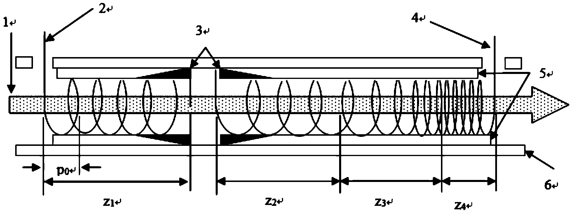
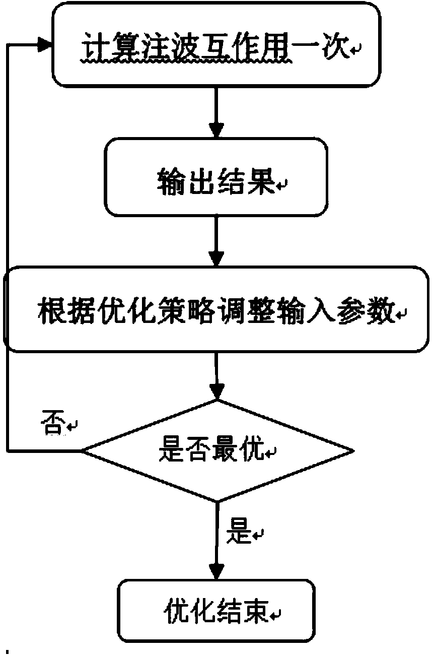
[0003] In the design process of traveling wave tubes, semi-analytical and semi-numerical parameter theoretical models are mainly used at present (see "A simulation method for injection-wave interaction in traveling wave tubes" patent CN201110236508.8, 2011, Hu Yulu, Peng Weifeng, Li Bin, etc.) for injection For the calculation of the wave interaction process, the single calculation time is about tens of seconds or even a few minutes, but the complex design of the injection-wave interaction distribution structure of the traveling wave tube (see figure 1 ) often requires a large number of cumbersome iterations of optimization algorithms for optimization calculations. Ordinary optimization algorithms regard the calculation of a beam-wave interaction process as a whole (see figure 2 ), as many as hundreds or thousands of iterations multiplied by the calculation time of a single injection-wave interaction will also bring tens of minutes to several hours of calculation time

Method used


Image

  • Optimization method of traveling-wave tube beam wave interaction distribution structure
  • Optimization method of traveling-wave tube beam wave interaction distribution structure
  • Optimization method of traveling-wave tube beam wave interaction distribution structure

Examples


Embodiment Construction

[0021] Below to figure 1 The optimization of the interaction distribution structure is taken as an example, and the present invention will be further described in conjunction with the accompanying drawings and specific implementation examples.

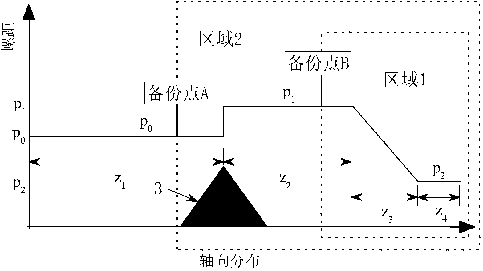
[0022] Specifically, it contains 6 variables (that is, the four distribution length variables z 1 ,z 2 ,z 3 ,z 4 and two pitch variables p 1 ,p 2 , where p 1 is the distribution length z 2 Partial pitch size, p 2 is the distribution length z 4 part of the pitch size), p 0 (distribution length z 1 Part of the pitch size) variables can be determined empirically or by appropriate scans, which can save optimization time. Divide the variables of these 6 interactive distribution structures into two parts, area 1 and area 2, for optimization, where area 2 nests and calls the optimization algorithm of the variables in area 1, and returns the best result of its optimization to the optimization in area 1 algorithm.

[0023] 1. Calcu...


PUM


Abstract

The invention discloses an optimization method of a traveling-wave tube beam wave interaction distribution structure. The optimization method of the traveling-wave tube beam wave interaction distribution structure aims to improve the optimization efficiency of a traveling-wave tube beam wave interaction optimization algorithm. The optimization method combines the optimization algorithm with the internal mechanism of beam wave interaction and relates to a nest algorithm, through the beam wave interaction process sequencing computation characteristic and whether the relative phase angle phi meets the condition that phi > pi / 2 or phi < -pi / 2, computation is ended in advance. For an ordinary high-efficiency screw pitch distribution structure, the efficiency of the optimization method is improved by three to four times compared with an ordinary optimization method.

Description

technical field [0001] The invention belongs to the technical field of traveling wave tubes, and in particular relates to a method for optimizing the injection wave interaction distribution structure of a traveling wave tube. Background technique [0002] Traveling wave tube is one of the most widely used vacuum electronic devices, widely used in satellite communication, radar, electronic countermeasures and other fields. At present, the use of computer-aided design (Computer Aided Design, CAD) technology is one of the main means to save costs, improve design and improve the overall performance of traveling wave tubes. In the CAD technology of traveling wave tubes, it is of great significance to analyze the interaction between electron beam and high-frequency electromagnetic field in traveling wave tube (namely beam interaction). The injection wave interaction in the traveling wave tube is a process in which the energy of the signal is amplified from left to right: the sign...

Claims


Application Information

Patent Timeline
Patent Type & Authority Applications(China)
IPC IPC(8): G06F17/50
Inventor 胡玉禄李斌李建清杨中海
Owner UNIV OF ELECTRONICS SCI & TECH OF CHINA
Learn More