Rollers

A technology of shaft center and connecting part, applied in the field of rollers, can solve the problems of chip collapse, inability to press the adhesive tape evenly, and poor sticking, etc.

Inactive Publication Date: 2014-07-23
DISCO CORP
View PDF10 Cites 3 Cited by
  • Summary
  • Abstract
  • Description
  • Claims
  • Application Information

AI Technical Summary

Problems solved by technology

[0011] However, when the adhesive tape is attached to a plate while pressing the adhesive tape with the squeegee, the squeegee slides against the adhesive tape, so the frictional force increases depending on the materials of the adhesive tape and the squeegee, and the squeegee slips. The adhesive tape cannot be pressed evenly, and there is a problem of poor adhesion
[0012] On the other hand, when the adhesive tape is attached to a plate while pressing it with a roller, the roller itself

Method used


Image

  • Rollers
  • Rollers
  • Rollers

Examples


Embodiment Construction

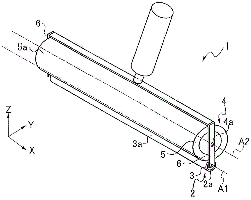
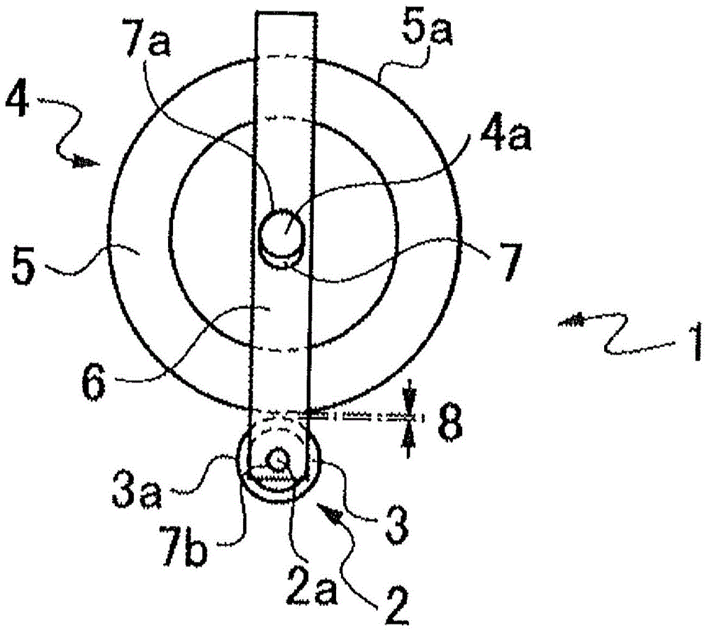
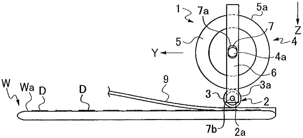
[0031] figure 1 The shown roller 1 is a first example of a roller for pressing an object such as an adhesive tape and sticking it to a plate-like object. The roller 1 includes: a pressing roller 2 for pressing an object; a deflection prevention roller 4 for preventing the deflection of the pressing roller 2; and a connecting portion 6 for rollingly connecting the pressing roller 2 and the deflection prevention roller 4 .

[0032] The pressing roller 2 includes a shaft portion 2 a having an axis A1 in the horizontal direction (X-axis direction), and an annular outer peripheral portion 3 , and the pressing roller 2 is rotatable about the axis A1 . At least the outer peripheral portion 3 of the pressing roller 2 is preferably formed by an elastic member. As the elastic member, for example, silicone rubber can be used. Furthermore, it is preferable that the pressing roller 2 is formed to have a small diameter, for example, a diameter of 6 mm to 8 mm. When the diameter of the p...


PUM

PropertyMeasurementUnit
Diameteraaaaaaaaaa

Abstract

The invention provides rollers which apply a pressing force uniformly on an object. The rollers comprise a pressing roller (2), a flexible prevention roller (4) having an axial center (A2) in parallel with an axial center (A1) of the pressing roller (2) and having a diameter larger than that of the pressing roller (2), and a connection part (6). The flexible prevention roller (4) is configured to be adjacent to the pressing roller (2) and can press the pressing roller (2) in a state that the periphery (5) of the flexible prevention roller (4) is abutted against the periphery (3) of the pressing roller (2). The connection part (6) connects the pressing roller and the flexible prevention roller. Thus, compared with one roller, the rollers are improved in rigidity and prevent slight flexure of the pressing roller. The pressing roller can apply a pressing force on a bonding belt, so that a bonding belt (9) can be adhered to a plate-shaped object (W) when bubbles are formed between the bonding belt (9) and a plate-shaped object (W).

Description

technical field [0001] The present invention relates to a roller for pressing an object such as an adhesive tape. Background technique [0002] Plates such as semiconductor wafers and optical device wafers having devices on the front side are ground and thinned from the back side, and then separated into individual chips using a cutting device or the like. Before grinding such a plate-shaped object, a front-side protection tape is attached to protect the device on the front of the plate-shaped object (for example, refer to Patent Document 1 below). [0003] When a plate-shaped object is divided into individual chips by a cutting device, a dicing tape having an adhesive layer on the surface is also attached to facilitate handling of the divided chips (see, for example, Patent Document 2 below). In addition, in the case of applying an external force to the plate-shaped object forming the starting point of division to divide the plate-shaped object into individual chips, after...

Claims


Application Information

Patent Timeline
IPC IPC(8): H01L21/78H01L21/67
CPCH01L21/67132H01L21/6836H01L2221/68327H01L21/67092
Inventor 高泽徹
Owner DISCO CORP
Why Eureka
Try Eureka