
A dual-channel unidirectional controlled energy storage inverter system

An energy storage inverter, one-way technology, applied in the direction of current collectors, energy storage, circuit devices, etc., can solve problems affecting the health and operation life of batteries, micro-grid paralysis, etc., to achieve enhanced black start capabilities and enhanced Rodability, life-enhancing effects

Active Publication Date: 2016-12-28
周锡卫
View PDF4 Cites 0 Cited by
  • Summary
  • Abstract
  • Description
  • Claims
  • Application Information

AI Technical Summary

Problems solved by technology

[0003] However, the energy storage inverters and system products seen in the existing technology and the market are mainly developed based on UPS technology for energy storage and backup. The energy storage part is composed of a set of batteries connected to the DC terminal of the bidirectional inverter circuit. Its disadvantage is that when there is a load that needs to supply power, even if the battery is charging, the battery will switch to the state of discharging, so that the battery pack is essentially not controlled by the charge and discharge control circuit, which seriously affects the healthy work and operating life of the battery. ; Moreover, in the microgrid, the energy storage inverter system is mainly responsible for supporting the grid environment of the microgrid. After the battery is discharged, a single battery pack needs to add a certain amount of electricity to make the inverter circuit work again and supply power. This is because the startup The voltage is higher than the minimum voltage that can be set for discharge. For this, if the new energy power generation is insufficient or does not generate power, it will affect the inverter circuit to start and work again, and even paralyze the microgrid

Method used


Image

  • A dual-channel unidirectional controlled energy storage inverter system
  • A dual-channel unidirectional controlled energy storage inverter system

Examples


Embodiment Construction

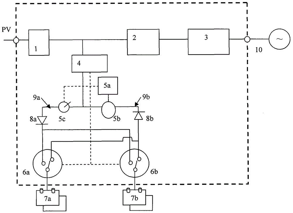
[0021] As an implementation example, a two-way unidirectional controlled energy storage inverter system is described with reference to the accompanying drawings, however, the technology and solution of the present invention are not limited to the content given in this implementation example.

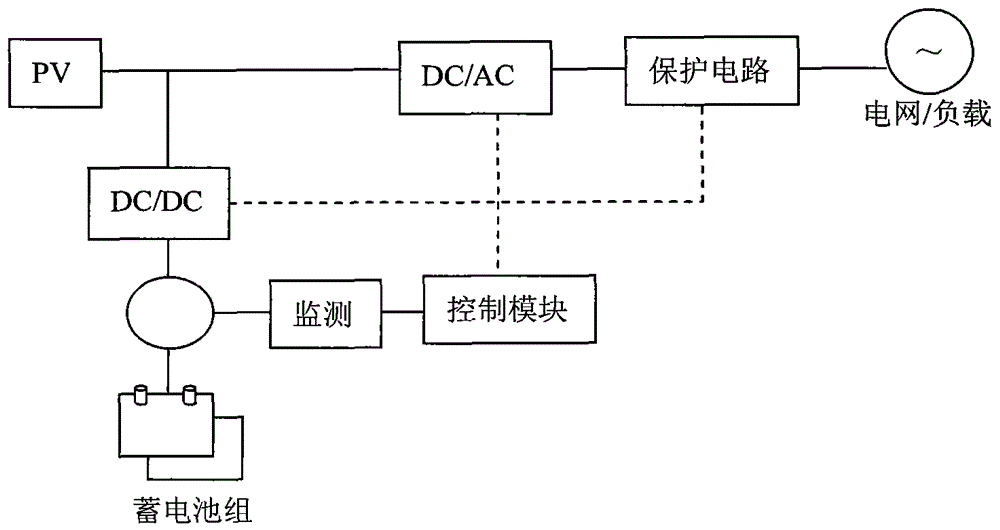
[0022] attached figure 1 A schematic diagram of the functional principle of the energy storage inverter system in the prior art is given. As shown in the figure, the energy storage inverter system in the prior art is composed of a group of batteries connected to the DC terminal of the bidirectional inverter circuit. The disadvantages are: When the load needs power supply, even if the battery is charging, the battery will switch to the state of discharging, so that the battery pack is essentially not controlled by the charge and discharge control circuit, which seriously affects the healthy work and operating life of the battery.

[0023] figure 2 A schematic diagram of the functional p...


PUM


Abstract

The invention belongs to the field of electric power energy storage inversion technologies and particularly relates to a double-channel unidirectional controlled energy storage inverter system. The double-channel unidirectional controlled energy storage inverter system comprises a photovoltaic and new energy access end, an MPPT and bidirectional DC / AC module, an alternating current protection and switching module, a charge and discharge module, a charge and discharge path regulation and control module, a discharge sensing circuit, a charge path switching circuit, a charge and discharge selective switch A, a charge and discharge selective switch B, a storage battery A, a storage battery B, a charge anti-countercurrent circuit, a discharge anti-countercurrent circuit, a charge bus, a discharge bus, a power grid and a load end. According to the system, two or more groups of storage batteries are utilized, a monitoring module is utilized to carry out real-time monitoring, the corresponding storage batteries in the charge and discharge states are controlled in a double-channel unidirectional controlled mode and the whole charge or discharge process is independently carried out in a corresponding state, so that the service lives of the storage batteries are prolonged, the reliability and security of the energy storage inverter system is improved, and the robustness and the black-start capability of the energy storage inverter system are enhanced.

Description

technical field [0001] The invention belongs to the technical field of energy storage inverters, and in particular relates to a two-way unidirectional controlled energy storage inverter system. Background technique [0002] The wide application of new energy power and micro-grid has promoted the development of energy storage inverters and systems, so many energy storage inverter products have appeared on the market. For example, the products of the world-renowned ABB company and the well-known Chinese inverter company "Sunshine Power" have provided support and made contributions to the grid-connection and networking of new energy power systems, as well as power generation and power supply. [0003] However, the energy storage inverters and system products seen in the existing technology and the market are mainly developed based on UPS technology for energy storage and backup. The energy storage part is composed of a set of batteries connected to the DC terminal of the bidire...

Claims


Application Information

Patent Timeline
Patent Type & Authority Patents(China)
IPC IPC(8): H02J3/32H02J7/00
CPCY02E10/56Y02E70/30
Inventor 周锡卫
Owner 周锡卫
Learn More